
Power dividing circuit, power divider and electronic equipment

A technology of power dividing circuit and inductance, which is applied in the direction of circuits, electrical components, fixed/insulated contact components, etc., can solve the problems of poor voltage standing wave ratio performance and poor isolation effect of power dividing circuits, so as to improve isolation and reduce volume , Improving the effect of VSWR performance

Pending Publication Date: 2022-02-08
SHENZHEN ZHENHUA FU ELECTRONICS
View PDF0 Cites 0 Cited by
  • Summary
  • Abstract
  • Description
  • Claims
  • Application Information

AI Technical Summary

Problems solved by technology

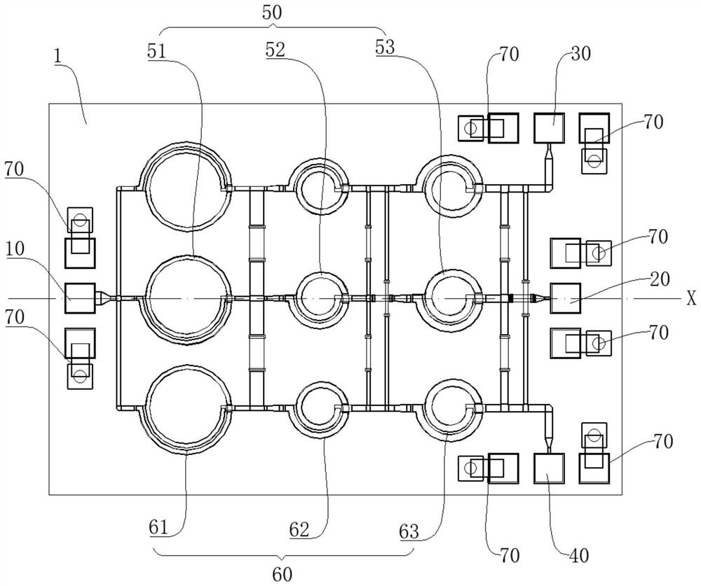
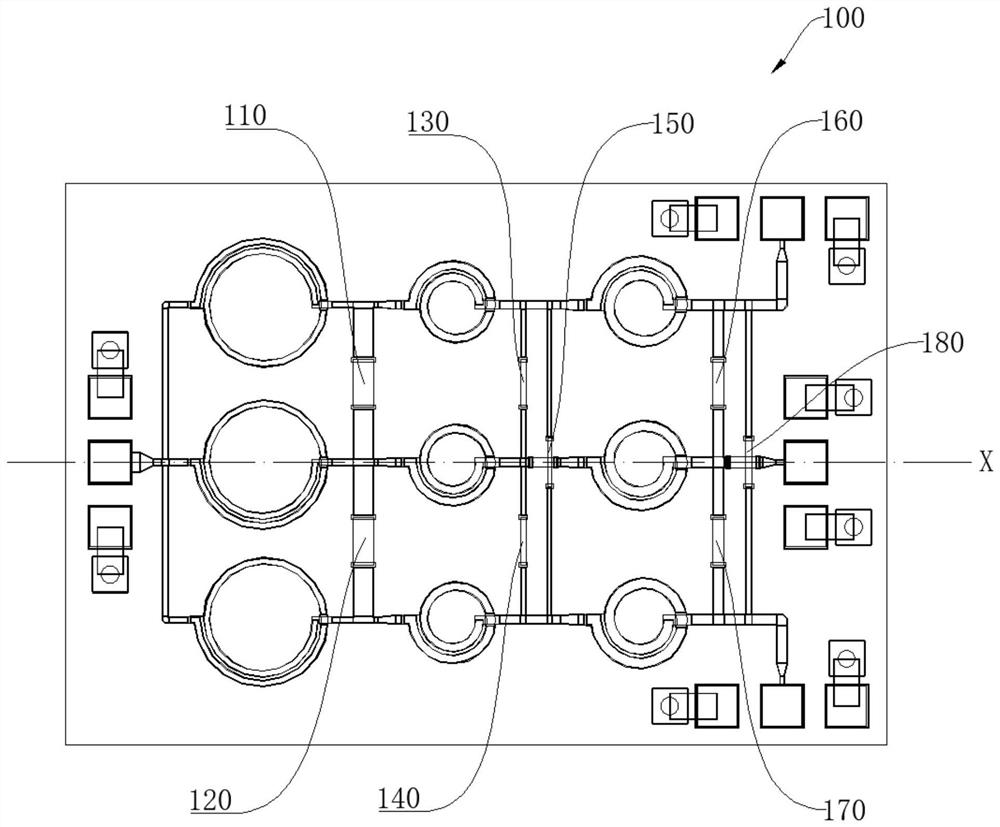
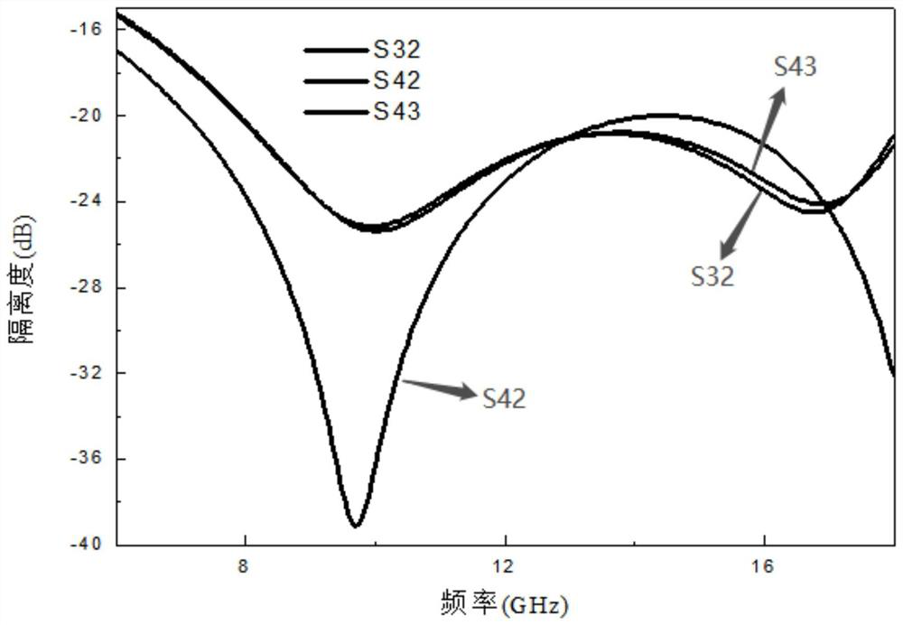
[0004] The embodiment of the present invention provides a power dividing circuit, a power dividing device and electronic equipment, which are used to solve the problems of poor isolation effect and poor voltage standing wave ratio performance of the traditional power dividing circuit after the volume becomes smaller

Method used


Image

  • Power dividing circuit, power divider and electronic equipment
  • Power dividing circuit, power divider and electronic equipment
  • Power dividing circuit, power divider and electronic equipment

Examples


Embodiment Construction

[0050] In order to facilitate the understanding of the present invention, the present invention will be described more fully below with reference to the associated drawings. Preferred embodiments of the invention are shown in the accompanying drawings. However, the present invention can be embodied in many other different forms and is not limited to the embodiments described herein. On the contrary, these embodiments are provided to make the understanding of the disclosure of the present invention more thorough and comprehensive.

[0051] It should be noted that when an element is referred to as being “fixed” or “disposed on” another element, it may be directly on the other element or be indirectly on the other element. When an element is referred to as being "connected to" another element, it can be directly connected to the other element or indirectly connected to the other element.

[0052] It is to be understood that the terms "length", "width", "top", "bottom", "front", "...


PUM

PropertyMeasurementUnit
Radiusaaaaaaaaaa
Radiusaaaaaaaaaa
Number of turnsaaaaaaaaaa

Abstract

The invention belongs to the field of power dividers, and relates to a power dividing circuit, a power divider and electronic equipment. According to the power dividing circuit, an input terminal, a first output terminal, a second output terminal, a third output terminal, a first power dividing component, two sets of second power dividing components and a resistive isolation component are integrated on the same dielectric plate through an integrated passive device technology, so that the power dividing circuit is minimized, and therefore, the size of the power dividing circuit is decreased; the first power dividing component is arranged along the center line of the input terminal, and the two sets of second power dividing components are symmetrically arranged relative to the center line of the input terminal, so that impedance matching from the input terminal to the first output terminal, from the input terminal to the second output terminal and from the input terminal to the third output terminal is achieved, the voltage standing wave ratio performance of the power dividing circuit is improved; the three output ends of the power dividing circuit are isolated by the resistive isolation component, and therefore the isolation degree of the power dividing circuit is improved.

Description

technical field [0001] The invention relates to the technical field of power dividers, in particular to a power divider circuit, a power divider and electronic equipment. Background technique [0002] The power divider is a device that divides the input power into several equal or unequal energies and outputs them. At this time, the function of the power divider is power distribution; at the same time, the power divider can also be reversed to combine multiple energies into one way. output, at this time the function of the power divider is power synthesis. Power splitters are widely used in radio frequency modules in wireless communication systems, such as antenna feed networks, mixers or power amplifiers, etc. The performance of power splitters directly affects the energy distribution and synthesis efficiency of the entire system. In addition, the current development trend of electronic products is miniaturization, so the power splitter also needs to be miniaturized. [0...

Claims


Application Information

Patent Timeline
IPC IPC(8): H01R25/16H01R13/40
CPCH01R25/161H01R13/40
Inventor 钟伦威刘季超肖倩李秀山徐鹏飞张玲玲田慧成
Owner SHENZHEN ZHENHUA FU ELECTRONICS
Learn More