Multifunctional pressure plate assembly for cutting machine

A cutting machine, multi-functional technology, applied in the cutting of textile materials, textile and papermaking, metal processing and other directions, can solve the problem that the single platen assembly cannot be accurately set, affecting the cutting efficiency and the quality of the cutting piece, the platen and the cutter head. Easy to fall off and other problems, to achieve the effect of improving cutting effect, preventing falling off and offset, and simplifying and stable structure

Pending Publication Date: 2022-02-11
武汉天铭智能设备有限公司
View PDF0 Cites 0 Cited by
  • Summary
  • Abstract
  • Description
  • Claims
  • Application Information

AI Technical Summary

Problems solved by technology

The inventor of this patent application has found in long-term production practice that the pressure plate assembly used for the cutter head of the cutting machine in the prior art is a single pressure plate structure, and there is no height-fixing function. The so-called height-fixing means that it can meet different The thickness of the cutting fabric is used to adjust the height of the cutting disc, and ensure high precision, improve the cutting effect and improve the quality of the cutting piece
However, the pressure plate assembly in the prior art does not have this function, and can only realize the height-fixing operation through other structures, such as a more complicated structure that drives the entire cutting machine head to rise and fall together, etc.
However, for the pressure plate assembly products of the single pressure plate structure in the prior art, there are the following disadvantages: 1, the single pressure plate assembly, the pressure plate and the cutter head are easy to fall off, and are prone to dysfunction; 2, the single pressure plate assembly The height cannot b

Method used


Image

  • Multifunctional pressure plate assembly for cutting machine
  • Multifunctional pressure plate assembly for cutting machine
  • Multifunctional pressure plate assembly for cutting machine

Examples


Embodiment Construction

[0023] The present invention will be described in further detail below in conjunction with the accompanying drawings.

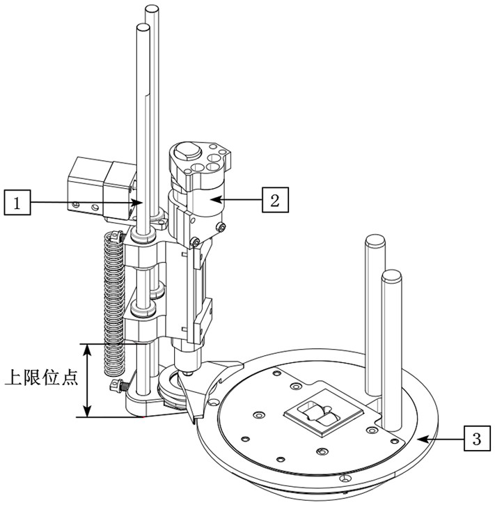
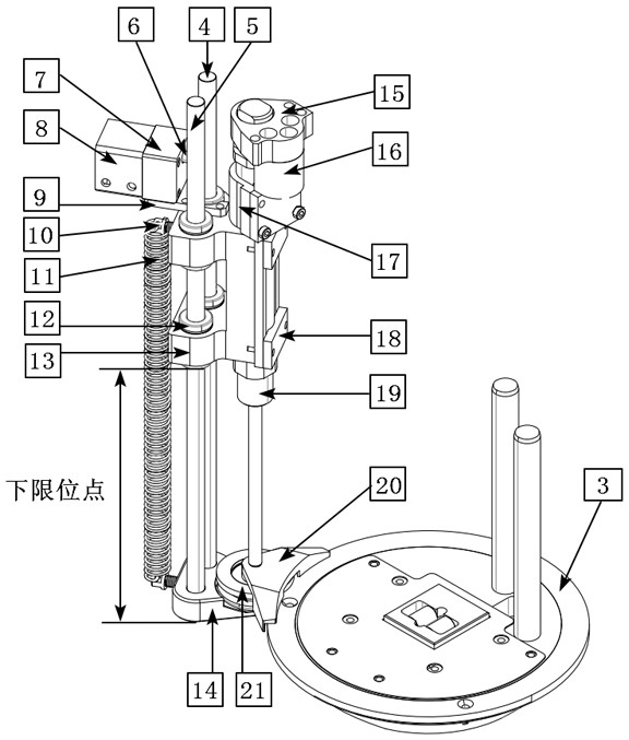
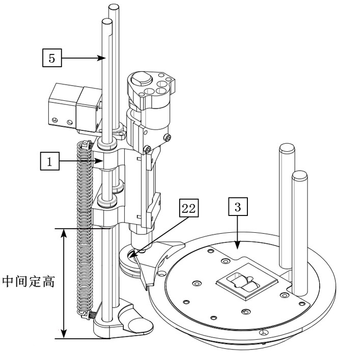
[0024] combined with Figures 1 to 4 , a multi-functional platen assembly for a cutting machine, which includes a height-fixing assembly 1 and a main platen assembly 2, the lower part of the main platen assembly 2 is provided to ensure that the cutter head assembly 3 of the cutting machine can rotate and cut smoothly The position-limiting mechanism; the height-fixing component 1 and the pressure plate main component 2 are installed side by side, the height-fixing component 1 is equipped with a supporting plate for supporting the position-limiting mechanism, and the supporting plate is connected on the supporting plate. A height-fixed telescopic device; after the height setting of the supporting plate, the working height of the limit mechanism and the cutter head assembly 3 is synchronized by supporting the limit mechanism.

[0025] As a preference, said plat...


PUM


Abstract

The invention discloses a multifunctional pressure plate assembly for a cutting machine. The multifunctional pressure plate assembly comprises a height fixing assembly and a pressure plate main assembly, wherein the lower part of the pressure plate main assembly is provided with a limiting mechanism for ensuring that a cutter head assembly of the cutting machine stably rotates and shears; the height fixing assembly and the pressure plate main assembly are installed side by side, a supporting plate used for bearing the limiting mechanism is installed on the height fixing assembly, and a telescopic device used for fixing the height of the supporting plate is connected to the supporting plate; and the supporting plate synchronizes the working heights of the limiting mechanism and the cutter head assembly by supporting the limiting mechanism after height setting. The multifunctional pressure plate assembly has the advantages that an auxiliary protection effect on the pressure plate can be achieved, and a cutter head is prevented from falling off and deviating; and high-quality tailoring of tailored fabrics with different thicknesses can be realized.

Description

technical field [0001] The invention relates to the technical field of cloth cutting machinery accessories, in particular to a pressure plate assembly used for a cutter head of a cutting machine. Background technique [0002] A cutting machine is a processing equipment that uses a motor to drive the cutting equipment to cut the cloth into the desired shape. Including electric scissors, punching machines and automatic cutting machines, etc. At present, in the fabric processing industry, automatic cutting machines are more common. There is an important part in the automatic cutting machine, which is the cutter head. In order to maintain the stability of the cutter head, the cutter head is equipped with a pressure plate assembly, which is used to press the cutter head to prevent the cutter head from shifting or falling off. The inventor of this patent application has found in long-term production practice that the pressure plate assembly used for the cutter head of the cuttin...

Claims


Application Information

Patent Timeline
IPC IPC(8): B26D7/26D06H7/00
CPCB26D7/2621B26D7/2635D06H7/00
Inventor 殷中波刘诗卉
Owner 武汉天铭智能设备有限公司
Why Eureka
Try Eureka