
Punching device for building wear-resistant material processing and using method of punching device

A technology of wear-resistant materials and punching devices, which is applied in the field of wear-resistant materials, can solve the problems of affecting the working environment, affecting the roughness of punching, working environment, material punching tool damage, etc., and achieves the effect of protecting quality

Inactive Publication Date: 2022-02-11
江苏首盾耐磨材料有限公司
View PDF0 Cites 0 Cited by
  • Summary
  • Abstract
  • Description
  • Claims
  • Application Information

AI Technical Summary

Problems solved by technology

[0003] Building wear-resistant materials need to be drilled when they are used, and a lot of heat and waste will be generated when drilling. High temperature will cause great damage to the material itself and the punching knife, and the waste will affect the roughness of the hole and the working environment.
In the prior art, the cutting fluid is sprayed on the processing surface to cool down and protect the tool and the processing surface at the same time, but the cutting fluid is often sprayed to the entire material surface, and the oil pollution on the material surface also affects the subsequent processing, and the drilling waste will pollute the air , affecting the working environment

Method used


Image

  • Punching device for building wear-resistant material processing and using method of punching device
  • Punching device for building wear-resistant material processing and using method of punching device
  • Punching device for building wear-resistant material processing and using method of punching device

Examples


Embodiment Construction

[0026] The technical solutions in the embodiments of the present invention will be clearly and completely described below in conjunction with the accompanying drawings in the embodiments of the present invention. Obviously, the described embodiments are only some of the embodiments of the present invention, not all of them; based on The embodiments of the present invention and all other embodiments obtained by persons of ordinary skill in the art without making creative efforts belong to the protection scope of the present invention.

[0027] It should be noted that the words "front", "rear", "left", "right", "upper" and "lower" used in the following description refer to the directions in the drawings, and the words "inner" and "outer ” refer to directions towards or away from the geometric center of a particular part, respectively.

[0028] Such as Figure 1~4As shown, the technical scheme adopted by the present invention is as follows: a drilling device for processing wear-...


PUM


Abstract

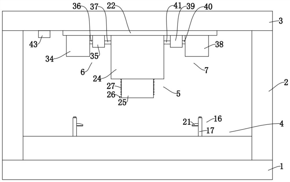
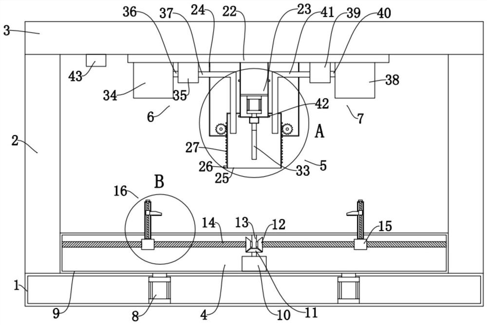
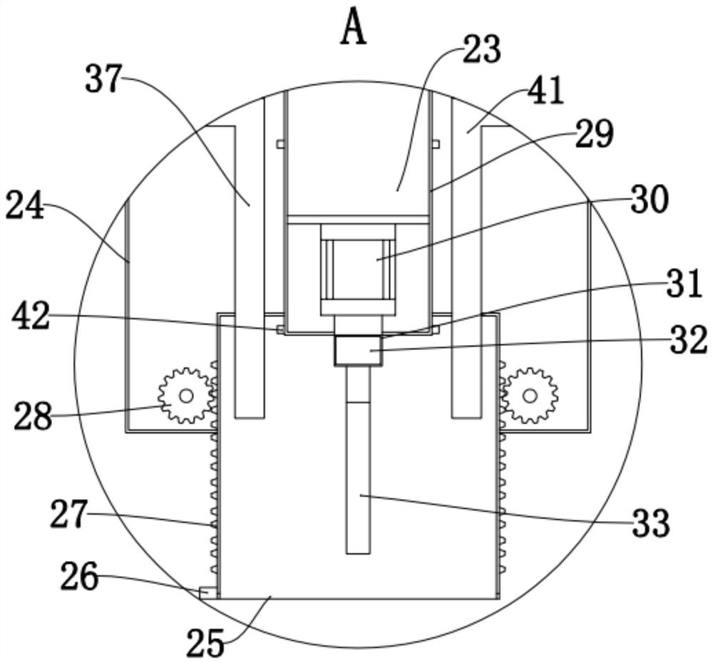
The invention discloses a punching device for building wear-resistant material processing and a using method of the punching device. The punching device comprises a device base, device side supporting plates, a device top plate, a lifting clamping structure, a punching structure, a cooling structure and a scrap removing structure, wherein two sets of device side supporting plates are arranged, the two sets of device side supporting plates are arranged on the two sides of the device base, the device top plate is arranged on the two sets of device side supporting plates, sliding grooves are formed in the side walls of the two sets of device side supporting plates, the lifting clamping structure is arranged in the sliding grooves in a sliding mode, the punching structure is arranged on the lower portion of the device top plate, and the cooling structure and the scrap removing structure are arranged on the punching structure and located on the two sides of the punching structure respectively. The invention relates to the technical field of wear-resistant materials, and particularly provides a punching device for building wear-resistant material processing, wherein the punching device can locally cool a wear-resistant material during punching and can completely recover cutting scraps to prevent air pollution.

Description

technical field [0001] The invention relates to the technical field of wear-resistant materials, in particular to a punching device for processing building wear-resistant materials and a method for using the same. Background technique [0002] Wear-resistant materials are a large class of new materials with special electrical, magnetic, optical, sound, heat, force, chemical and biological functions. There are many types of wear-resistant materials and they have a wide range of uses. They play an important role in agriculture, chemical industry, building materials and other fields. At present, wear-resistant materials mainly include the following categories: wear-resistant balls, wear-resistant steel plates, wear-resistant welding rods, wear-resistant ceramics, wear-resistant floors, wear-resistant rubber, wear-resistant pipes, wear-resistant bearings, wear-resistant welding materials, Wear-resistant castings, cast stones, polymers, composite wear-resistant materials and othe...

Claims


Application Information

Patent Timeline
IPC IPC(8): B28D1/14B28D7/00B28D7/02B28D7/04B26F1/16B26D5/08B26D7/08B26D7/02B26D5/06
CPCB28D1/14B28D7/00B28D7/02B28D7/005B28D7/04B26F1/16B26D5/08B26D7/08B26D7/02B26D5/06
Inventor 单东峰
Owner 江苏首盾耐磨材料有限公司
Learn More