

Petroleum pipeline installation lifting appliance capable of achieving closed polishing
A technology for oil pipeline and installation, which is applied in the field of spreaders for oil pipeline installation, and can solve problems such as violent shaking of oil pipelines, deformation of oil pipelines, and influence on construction efficiency
- Summary
- Abstract
- Description
- Claims
- Application Information
AI Technical Summary
Problems solved by technology
Method used
Image

Examples
Embodiment 1
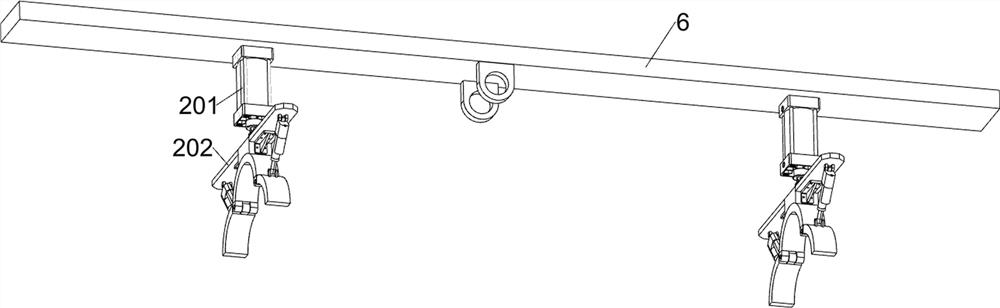
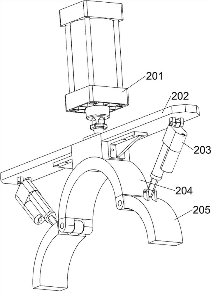
[0038] A kind of spreader that can be closed and polished for oil pipeline installation, such as Figure 1-3 As shown, it includes a lifting ring 1, a fixing column 2, a first lug 3, a sling 4, a second lug 5, a support beam 6, a third lug 7, an anti-bending system, a sealing grinding system, a propulsion system and a fixed system; the bottom of the lifting ring 1 is welded with a fixed column 2; the left and right sides of the fixed column 2 are respectively welded with a first hanging lug 3; the outer sides of the two first hanging lugs 3 are connected with a lifting rope 4; A second hanging lug 5; a supporting beam 6 is welded between the bottoms of the two second hanging lugs 5; a third hanging lug 7 is welded on the front and rear sides of the middle of the lower surface of the supporting beam 6; the left and right sides of the lower surface of the supporting beam 6 Attached with anti-bending system.
[0039] First, hang the device on the hook of the peripheral hoisting ...
Embodiment 2
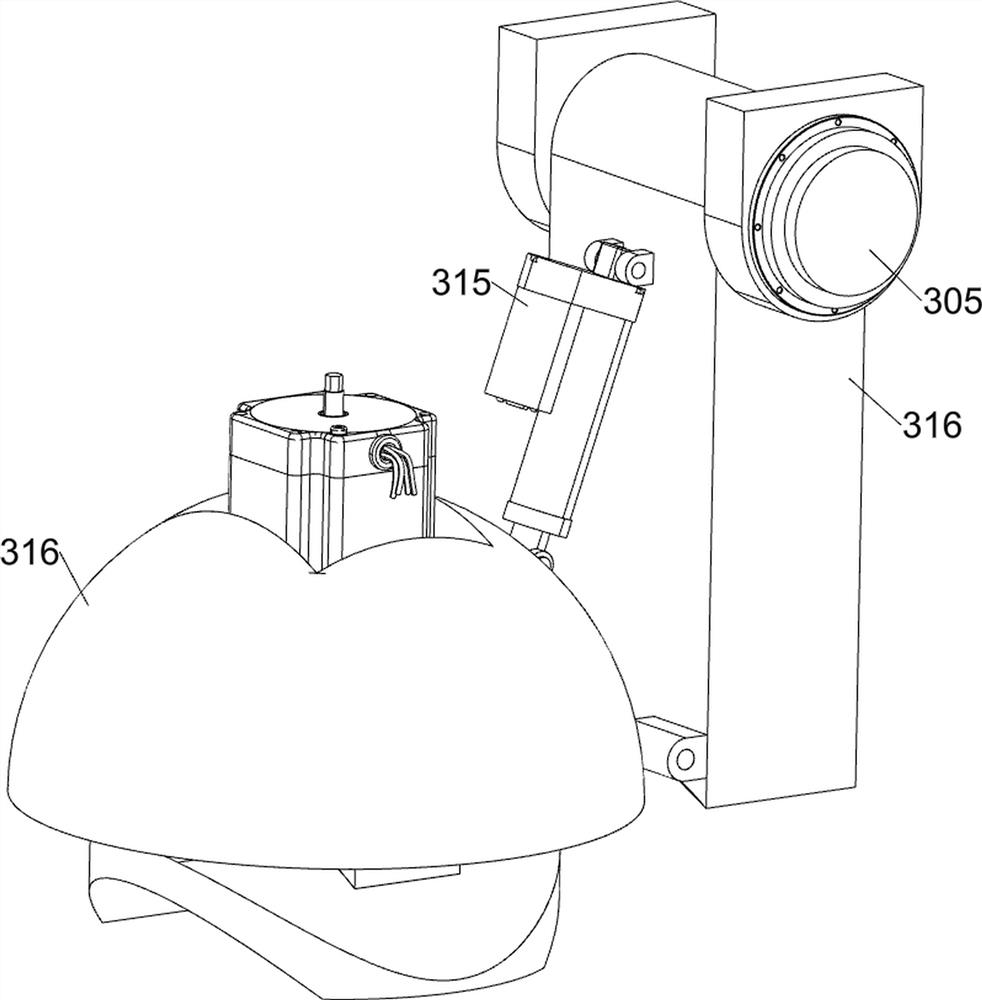
[0045] On the basis of Example 1, such as figure 1 and Figure 6-8 As shown, it also includes a sealing grinding system; the lower surface of the support beam 6 is connected to the sealing grinding system on the left side of the anti-bending system; the sealing grinding system includes a first electric slide rail 301, a first electric slider 302, a first installation Plate 303, first linkage plate 304, first electric shaft 305, first support base 306, second mounting plate 307, second electric push rod 308, second limit seat 309, second support arc plate 310, first The lifting plate 311, the third mounting plate 312, the first elastic member 313, the first clamping member 314 and the grinding assembly; the lower surface of the support beam 6 and the first electric slide rail 301 is connected with the bolt on the left side of the anti-bending system; the first The bottom of the electric slide rail 301 is slidingly connected with a first electric slider 302; the lower surface o...
Embodiment 3
[0055] On the basis of Example 2, such as figure 1 and Figure 11 As shown, a propulsion system is also included; the lower surface of the support beam 6 is connected to the propulsion system on the right side of the anti-bending system; the propulsion system includes a second electric slide rail 401, a second electric slide block 402, a fourth mounting plate 403, The second electric rotating shaft 404, the second support seat 405, the push column 406, the second windproof seat 407 and the second lifting plate 408; the lower surface of the support beam 6 and the second electric slide rail 401 are connected with bolts on the right side of the anti-bending system; The bottom of the second electric slide rail 401 is slidingly connected with a second electric slider 402; the lower surface of the second electric slider 402 is fixedly connected with a fourth mounting plate 403; the lower surface of the fourth mounting plate 403 is equipped with a second electric rotating shaft 404; ...
PUM
 Abstract
Description
Claims
Application Information