
Magnetic suspension bearing-based thrust vectoring nozzle for rocket projectile

A magnetic levitation bearing and thrust vectoring technology, which is applied in the field of vector nozzles, can solve the problems such as the difficulty of designing the control actuation system to be light, the cost and the weight of the aircraft, and achieve high utilization of axial space, high critical rotor speed, and improved performance. The effect of changing direction

Pending Publication Date: 2022-02-11
唐晓川 +4
View PDF0 Cites 0 Cited by
  • Summary
  • Abstract
  • Description
  • Claims
  • Application Information

AI Technical Summary

Problems solved by technology

The complex actuating parts of the baffle mechanically adjusted vector nozzle lead to an increase in cost and weight of the aircraft. The spherical convergence adjustment plate uses a spherical structure to make the force reasonable, but its control and actuation system is difficult to design lightly. So far, no payment has been made. Various practical designs, and the use of binary and axisymmetric vector nozzles can greatly reduce the cost and weight of the nozzle, and the reliability, maintainability and service life of the system have been greatly improved. At the same time, the infrared stealth performance of the nozzle It has also been strengthened. The axisymmetric relative binary nozzle only has the function of pitching thrust steering, which can realize all-round maneuverability. Therefore, the huge benefits brought by the axisymmetric vector nozzle have attracted the attention of all countries in the world, and priority is given to the development of the axisymmetric vector nozzle. Tube technology has become the consensus of the international aviation community

Method used


Image

  • Magnetic suspension bearing-based thrust vectoring nozzle for rocket projectile
  • Magnetic suspension bearing-based thrust vectoring nozzle for rocket projectile
  • Magnetic suspension bearing-based thrust vectoring nozzle for rocket projectile

Examples


Embodiment Construction

[0028] Embodiments of the present invention are described with reference to the accompanying drawings.

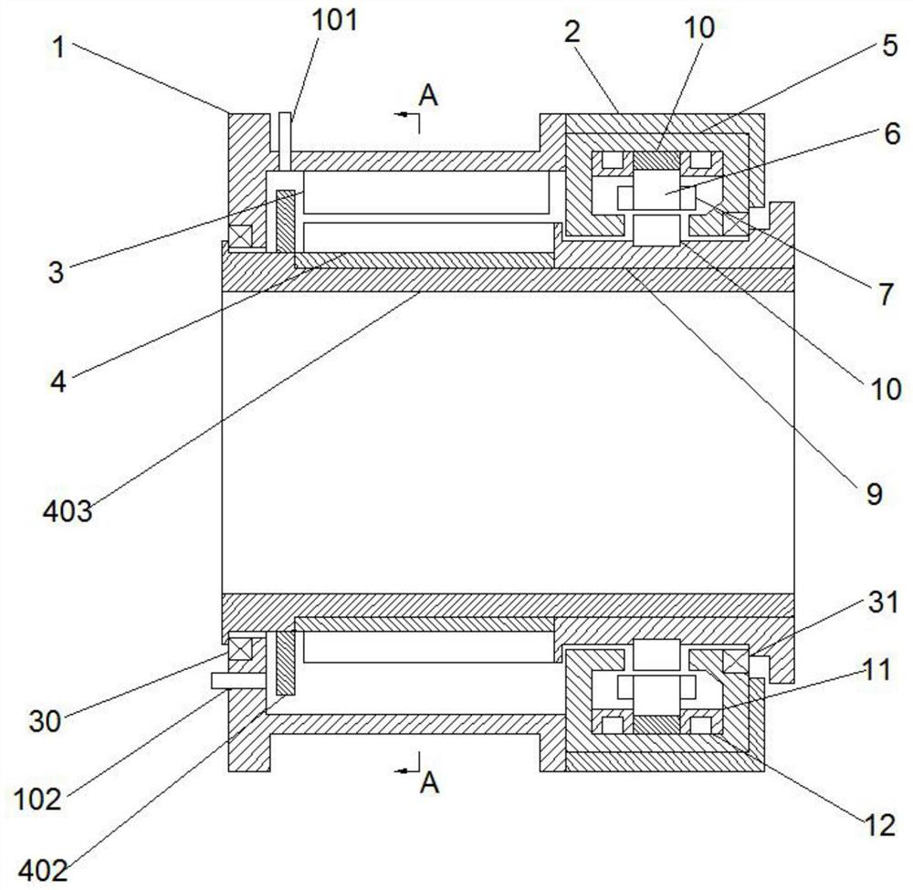
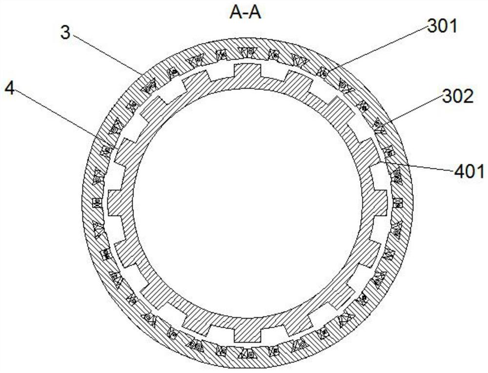
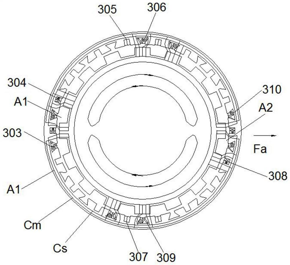
[0029] A thrust vectoring nozzle for rockets based on magnetic suspension bearings, including a secondary motor 1, the secondary motor 1 includes two parts: a motor body and a magnetic suspension bearing, the motor body includes two parts: a motor stator 3 and a motor rotor 4, and the motor stator is divided into three parts It consists of two parts, the suspension tank 301 and the rotation tank 302. The suspension coils represented by the first suspension wire package 304, the second suspension wire package 305, the third suspension wire package 307 and the fourth suspension wire package 308 are installed in the suspension tank 301. The suspension wire package is composed of two rectangular coils in series, and the two adjacent suspension wire packages are connected by the connection method of "head joint, tail to tail". The first rotating wire package 303 and the second ro...


PUM


Abstract

The invention provides a thrust vectoring nozzle based on a magnetic suspension bearing for a rocket projectile, and belongs to the technical field of vectoring nozzles. A large-aperture torque motor is designed based on a switched reluctance technology and a magnetic suspension technology, and is obliquely mounted at a joint of an irregular nozzle interface to drive a nozzle to realize hemispherical deflection in a space. In order to reduce the risk of motor demagnetization possibly caused by high-temperature flames in a spray pipe, a torque motor adopts a switched reluctance technology, namely, a motor rotor and a magnetic bearing rotor are formed by laminating high-temperature-resistant silicon steel materials, and the problem that precise transmission mechanisms are stuck due to metal material deformation possibly caused by high temperature and high pressure is solved. A motor rotor and stator non-contact magnetic suspension system is designed, the magnetic suspension system comprises a main suspension part and an auxiliary suspension part, the main suspension mechanism is a magnetic suspension bearing, the radial excitation and axial excitation coupling technology is adopted in the main suspension mechanism, the auxiliary suspension mechanism is located in the motor stator, and torque offset caused by the single-side acting force of the magnetic suspension bearing is eliminated.

Description

technical field [0001] The invention relates to the technical field of vectoring nozzles, in particular to a thrust vectoring nozzle for rockets based on magnetic suspension bearings. Background technique [0002] The implementation methods of thrust vectoring include: baffle plate, binary vector nozzle, axisymmetric vector nozzle, and spherical convergence regulating plate vector nozzle. The complex actuating parts of the baffle mechanically adjusted vector nozzle lead to an increase in cost and weight of the aircraft. The spherical convergence adjustment plate uses a spherical structure to make the force reasonable, but its control and actuation system is difficult to design lightly. So far, no payment has been made. Various practical designs, and the use of binary and axisymmetric vector nozzles can greatly reduce the cost and weight of the nozzle, and the reliability, maintainability and service life of the system have been greatly improved. At the same time, the infrare...

Claims


Application Information

Patent Timeline
Patent Type & Authority Applications(China)
IPC IPC(8): F02K9/90F02K9/97H02N15/00H02K3/28
CPCF02K9/805F02K9/90F02K9/97H02N15/00H02K3/28
Inventor 唐晓川吴晓中陆琤张君王婧懿
Owner 唐晓川
Learn More