Novel gas turbine low-pressure compressor rotor structure and assembling method

A technology for compressor rotors and gas turbines, which is applied in the direction of machines/engines, liquid fuel engines, mechanical equipment, etc. It can solve the problems of many parts, affecting the centering and balance of rotors, and uncontrollable quality, so as to reduce the number and reduce leakage. The effect of air loss and reliable force transmission

Active Publication Date: 2022-02-11
成都中科翼能科技有限公司
View PDF10 Cites 4 Cited by
  • Summary
  • Abstract
  • Description
  • Claims
  • Application Information

AI Technical Summary

Problems solved by technology

There are many parts in the drum rotor, and the manufacturing deviation will affect the centering and balance of the rotor, resulting in uncontrollable quality during production. This is a technical problem that needs to be solved urgently

Method used


Image

  • Novel gas turbine low-pressure compressor rotor structure and assembling method
  • Novel gas turbine low-pressure compressor rotor structure and assembling method
  • Novel gas turbine low-pressure compressor rotor structure and assembling method

Examples


Embodiment 1

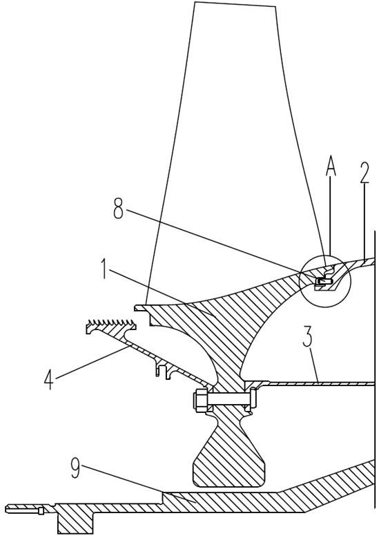
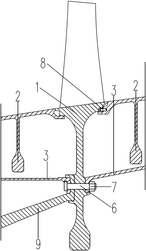
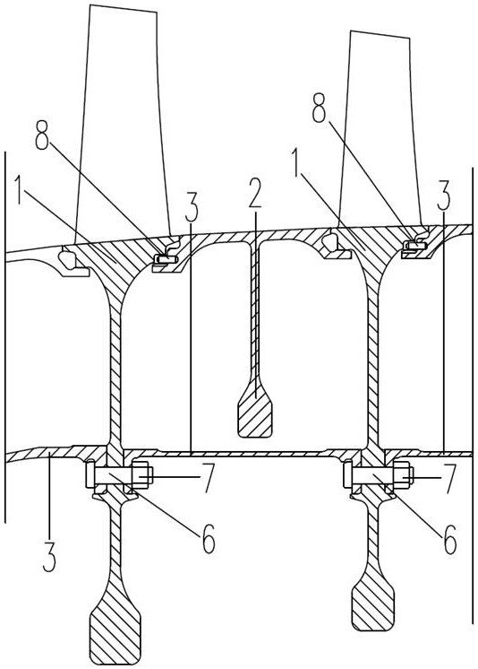
[0026] Such as Figure 1-5 As shown, the present embodiment provides a novel gas turbine low-pressure compressor rotor structure, including one to six working impellers 1 installed on the low-pressure compressor shaft and sequentially arranged from the front end to the rear end of the low-pressure compressor. The rotating shaft connects the working impellers 1 at all levels into one body and the associated structures into one.

[0027] Wherein, the outer sides of any adjacent two-stage working impellers 1 are connected by a passage ring assembly 2, and the inner sides of any adjacent two-stage working impellers 1 are connected by a spacer ring assembly 3, so that the two adjacent The first-stage working impellers 1 can be stably connected together, so that the first to sixth-stage working impellers 1 are combined into a stable whole; The end of the sixth-stage working impeller 1 close to the rear end of the low-pressure compressor is connected with the rear sealing grate toot...

Embodiment 2

[0037] This embodiment provides a method for assembling the rotor structure of a novel gas turbine low-pressure compressor as described in Embodiment 1, including the following specific steps:

[0038] Before assembly, put the low-pressure compressor shaft, first to sixth stage working impellers 1, all passage ring components 2, all spacer ring components 3, front sealing grate tooth disc 4, rear sealing grate tooth disc 5, all bolts 6. All lock nuts 7 and all pins 8 are aligned in place according to the installation position;

[0039] When assembled in place, rotate the working impeller 1, the passage ring assembly 2, the spacer ring assembly 3, the front sealing grate tooth plate 4, the rear sealing grate tooth plate 5, the front journal of the low-pressure compressor 9 and the rear journal of the low-pressure compressor The angular position of 10 to ensure the amount of runout.

[0040] When assembling, pre-tighten all the lock nuts 7 on the corresponding bolts 6 according...


PUM


Abstract

The invention discloses a novel gas turbine low-pressure compressor rotor structure and an assembling method. The rotor structure comprises one to six stages of working impellers, and two adjacent stages of working impellers are connected through a passage ring assembly and a distance ring assembly; the first-stage working impeller is connected with a front sealing labyrinth disc, and the sixth-stage working impeller is connected with a rear sealing labyrinth disc; the distance ring assembly and the working impeller are connected through a bolt, and a locking nut is screwed in the bolt. The passage ring assembly is connected with the working impeller through a pin, a pin hole is formed between the passage ring assembly and the working impeller, and swing gaps are formed between the pin and the pin hole and between the passage ring assembly and the working impeller. The assembling method comprises the following steps of aligning all the parts in places; and pre-tightening the locking nut on the bolt, unscrewing for two circles after 20-30 minutes, and finally and tightly screwing in. According to the present invention, centering and torque transmission between parts are guaranteed, and good centering and reliable force transmission can be achieved.

Description

technical field [0001] The invention belongs to the technical field of gas turbines, and in particular relates to a novel gas turbine low-pressure compressor rotor structure and an assembly method. Background technique [0002] The compressor rotor is an assembly that rotates at high speed to work the airflow. Under the high-speed condition of the existing compressor rotor, the rotor parts and their joints have to bear huge inertia force and gas force. The existing drum rotor, the basic component of the drum rotor is a cylindrical, olive or conical structure, which is connected to the front and rear axle shafts by means of mounting edges and bolts. This structure has poor centrifugal load capacity, so it can only be used at peripheral speeds. Use under low conditions (not greater than 180-200m / s). Such as the early compressor, the low-pressure rotor of the modern high-flow compressor turbofan engine. The rotors of low-pressure compressors for civil Spey engines are all dr...

Claims


Application Information

Patent Timeline
Patent Type & Authority Applications(China)
IPC IPC(8): F04D29/32F04D29/64F01D11/02F01D11/08
CPCF04D29/321F04D29/644F01D11/02F01D11/08
Inventor 方圆王鸣王梁丞赵芳亮梁豪豪闪颂武杨万金
Owner 成都中科翼能科技有限公司
Why Eureka
Try Eureka