
Relay adhesion diagnosis method and device based on coil current characteristics

A technology of coil current and diagnosis method, applied in measuring devices, circuit breaker testing, instruments, etc., can solve problems such as inability to effectively distinguish main relay adhesion or pre-charged relay adhesion, side relay adhesion, safety hazards, etc., and achieve detailed positioning The effect of adhesion fault and easy fault diagnosis

Pending Publication Date: 2022-02-11
JIANGSU ZENIO NEW ENERGY BATTERY TECH CO LTD
View PDF0 Cites 1 Cited by
  • Summary
  • Abstract
  • Description
  • Claims
  • Application Information

AI Technical Summary

Problems solved by technology

Since the pre-charging relay is connected in parallel with the main circuit relay, most of the current mainstream relay sticking diagnosis technologies cannot effectively distinguish between the main relay sticking and the pre-charging relay sticking. charge and negative)
[0003] At present, there is still a way to distinguish pre-charging by closing the opposite side relay, such as pre-charging and connecting the positive pole, judging that the positive pole is sticking and then closing the total negative relay, and then judging whether there is a pre-charging process according to the Pack voltage and the main circuit current curve (current peak value is small, falling Slow) or the main (large current peak value, fast drop) relay adhesion, but this method is likely to cause the opposite side relay adhesion and the breakdown of the pre-charged capacitor, which poses a serious safety hazard

Method used


Image

  • Relay adhesion diagnosis method and device based on coil current characteristics
  • Relay adhesion diagnosis method and device based on coil current characteristics
  • Relay adhesion diagnosis method and device based on coil current characteristics

Examples


Embodiment

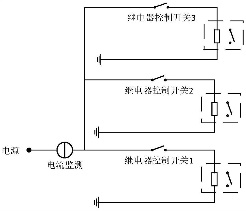
[0050] Such as figure 1 As shown, the device for diagnosing relay sticking based on coil current characteristics in this embodiment includes at least one current monitoring device and one relay control switch in the relay control loop. The relay control switch can control the high side, the low side or the high and low sides at the same time, and the current monitoring device can be connected in series to control the high side or the low side of the loop. When a system needs to control multiple relays, the current monitoring device can be multiplexed, such as figure 2 shown.

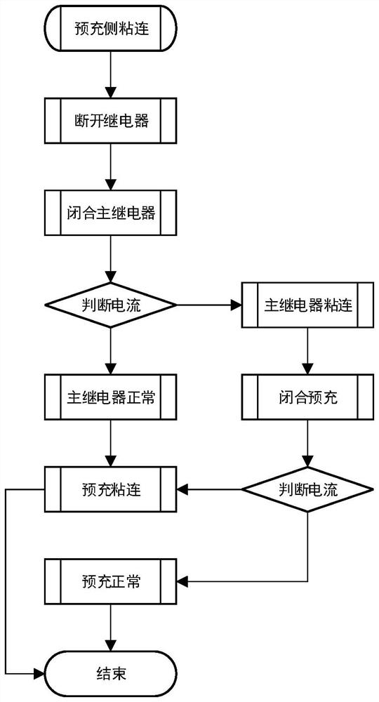
[0051]The relay sticking diagnosis device based on the coil current characteristics in this embodiment is mainly used to distinguish the sticking of the pre-charging relay and the main relay. It can be used after the sticking of the pre-charging side relay is determined by a relatively simple voltage method. The diagnosis process is as follows image 3 :

[0052] 1) Judgment of positive electrode adh...


PUM


Abstract

The invention discloses a relay adhesion diagnosis method and device based on coil current characteristics. The device comprises at least one current monitoring device and a relay control switch which are arranged in a relay control loop. When adhesion of a pre-charging side is judged through a voltage method, a main positive relay, a main negative relay and a pre-charging relay are switched off through the relay control switch; then, the pre-charging side main relay is controlled to be closed, meanwhile, the coil current of the pre-charging side main relay is monitored through a current monitoring device, whether the pre-charging side main relay is adhered or not is judged according to the coil current, and if not, it is judged that the pre-charging side main relay is adhered; if yes, power supply of a coil of the main relay on the pre-charging side is cut off, the pre-charging relay is closed, coil current of the pre-charging relay is monitored through a current monitoring device, and whether the pre-charging relay is adhered or not is judged according to the coil current. The device is used for safely and reliably distinguishing the adhesion of the pre-charging relay and the adhesion of the main loop relay so that the adhesion fault is more accurately and detailedly positioned.

Description

technical field [0001] The invention relates to the field of battery management systems (BMS) of new energy vehicles, in particular to a relay adhesion diagnosis method and device based on coil current characteristics. Background technique [0002] The intelligence of new energy vehicles is getting higher and higher, and the accuracy and accuracy of fault diagnosis are also getting higher and higher. Since the pre-charging relay is connected in parallel with the main circuit relay, most of the current mainstream relay sticking diagnosis technologies cannot effectively distinguish between the main relay sticking and the pre-charging relay sticking. charge and negative). [0003] At present, there is still a way to distinguish pre-charging by closing the opposite side relay, such as pre-charging and connecting the positive pole, judging that the positive pole is sticking and then closing the total negative relay, and then judging whether there is a pre-charging process accord...

Claims


Application Information

Patent Timeline
IPC IPC(8): G01R31/327
CPCG01R31/3278
Inventor 徐军平王志刚彭焓
Owner JIANGSU ZENIO NEW ENERGY BATTERY TECH CO LTD
Learn More