
Machine tool for machining turbine blades

A technology of blades and turbines, which is applied in the direction of metal processing machinery parts, metal processing, metal processing equipment, etc., can solve the problems of the final workpiece processing accuracy, inconvenient operation, etc., and achieve the effect of reducing space interference and iron filings splashing

Active Publication Date: 2022-02-15
爱派尔(常州)数控科技有限公司
View PDF12 Cites 3 Cited by
  • Summary
  • Abstract
  • Description
  • Claims
  • Application Information

AI Technical Summary

Problems solved by technology

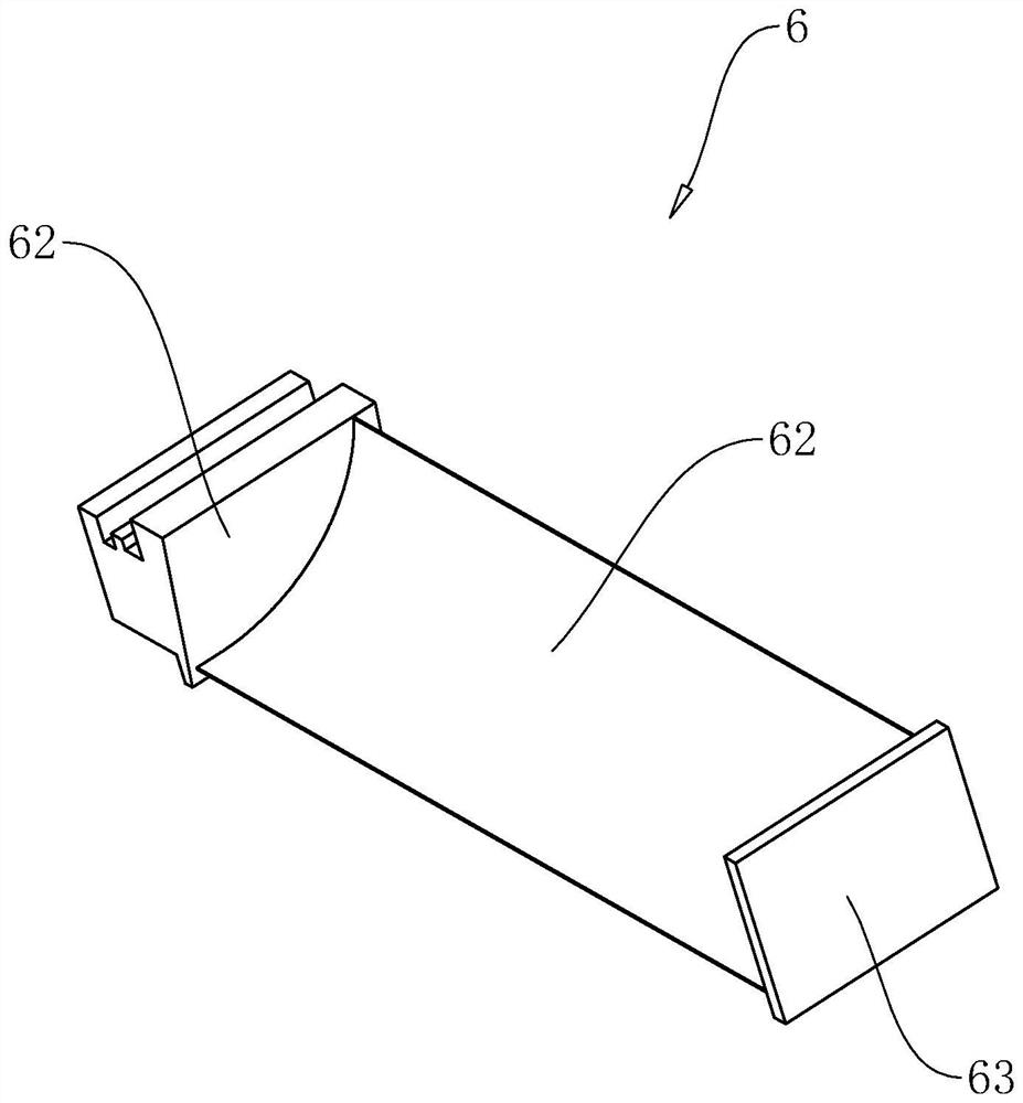
The airfoil 62 is a long plate with an arc surface, and the side surface of the blade root 61 facing the airfoil 62 is not perpendicular to the length direction of the airfoil 62, then when the workpiece blank is placed on the machine tool, the blade root The side of 61 facing the blade body 62 forms a blind area for the relative milling cutter along its axial direction. In order to realize complete processing, it is necessary to constantly adjust the placement angle of the blade blank, which is inconvenient to operate and negatively affects the processing accuracy of the final workpiece. Influence

Method used


Image

  • Machine tool for machining turbine blades
  • Machine tool for machining turbine blades
  • Machine tool for machining turbine blades

Examples


Embodiment Construction

[0033] The following is attached Figure 1-5 The application is described in further detail.

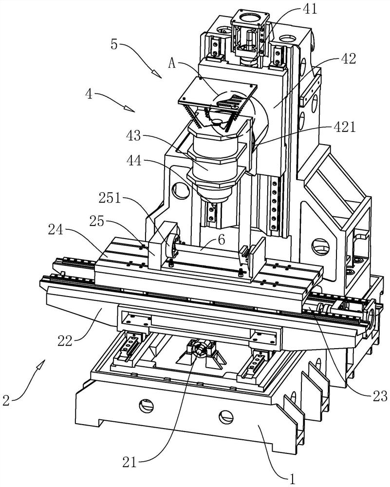
[0034] The embodiment of the present application discloses a machine tool for turbine blade processing, such as figure 2 As shown, it includes a frame 1, and the frame 1 is provided with a placement mechanism 2, a cutting mechanism 4 and a chip removal mechanism 5; the placement mechanism 2 is used to fix and adjust the attitude of the blade workpiece 6, and the cutting mechanism 4 includes a processing tool 44, It is used for milling the blade workpiece 6 , the machining tool 44 is a milling cutter, and the chip removal mechanism 5 is used for cleaning the iron filings generated during processing.

[0035] like figure 2 As shown, the placement mechanism 2 includes a first screw mandrel 21, a mounting base 22, a second screw mandrel 23 and a placement table 24, the mounting base 22 is slidably connected to the frame 1, and the first screw mandrel 21 is rotationally connected to t...


PUM


Abstract

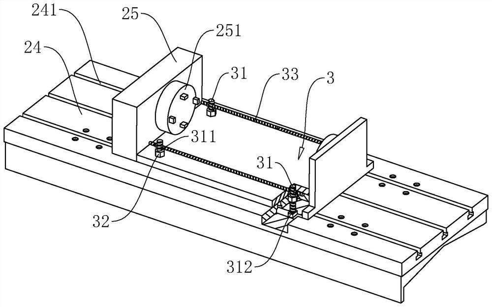
The invention relates to a machine tool for machining turbine blades, and belongs to the field of machining machine tools. The machine tool comprises a rack, a placing table and a cutting mechanism are arranged on the rack, the placing table is in sliding connection with the rack, the moving direction of the placing table is parallel to the table top, a turning frame is arranged on the placing table, an adjusting clamp is arranged on the turning frame, and the adjusting clamp is used for clamping blade workpieces; the adjusting clamp and the turning frame rotate relatively, and the rotating axis is consistent with the blade body length direction of the blade workpieces; the cutting mechanism comprises a cutting sliding table and a fixing block, the cutting sliding table slides relative to the rack, the sliding direction of the cutting sliding table is perpendicular to the table top of the containing table, the machining tool is rotationally connected to the side, facing the blade workpieces, of the fixing block, the fixing block is rotationally connected with the cutting sliding table, and the rotating axis of the fixing block is perpendicular to the blade body length direction of the blade workpieces. A five-axis machine tool for conducting all-dimensional machining on the blade sis established, operation convenience and operation efficiency of machining the surfaces of the blade workpieces by the machining tool are improved, and machining precision is improved.

Description

technical field [0001] The present application relates to the field of machine tools, in particular to a machine tool for machining turbine blades. Background technique [0002] The blades of the turbine are an important component of the turbine. Taking a gas turbine as an example, the gas generated after the fuel and air in the internal combustion engine are mixed and burned pushes the blades of the turbine, thereby realizing the conversion of mechanical kinetic energy. [0003] The blade workpiece 6 of the turbine blade in the related art is as figure 1 As shown, it includes a blade root 61, a blade body 62 and a blade crown 63. The blade root 61 and the blade crown 63 are respectively located at both ends of the blade body 62 in the length direction. Common blades are processed and integrally formed by a milling machine. The airfoil 62 is a long plate with an arc surface, and the side surface of the blade root 61 facing the airfoil 62 is not perpendicular to the length d...

Claims


Application Information

Patent Timeline
Patent Type & Authority Applications(China)
IPC IPC(8): B23D79/00B23Q11/00B23Q15/26
CPCB23D79/00B23Q15/26B23Q11/0064Y02P70/10
Inventor 邹简华
Owner 爱派尔(常州)数控科技有限公司
Learn More