Auxiliary device for maintenance of luffing mechanism and gantry crane

A technology of luffing mechanism and auxiliary device, which is applied in the direction of crane, load block, transportation and packaging, etc., and can solve the problems of dispatching external equipment and arranging auxiliary structures, a large number of tooling and welding work, more labor and maintenance time, etc. Achieve the effects of reducing space interference, improving efficiency, and saving cumbersome operations

Inactive Publication Date: 2020-09-22
QINGDAO HAIXI HEAVY DUTY MASCH CO LTD
View PDF0 Cites 0 Cited by
  • Summary
  • Abstract
  • Description
  • Claims
  • Application Information

AI Technical Summary

Problems solved by technology

[0004] The inventor found that there are many deficiencies in the maintenance of the luffing mechanism of the portal crane at present: 1. The maintenance operation is inconvenient. The luffing mechanism needs to be lifted and transferred by external equipment during maintenance. During the hoisting process, the column, wire rope, balance Due to the space interference of beams and other components, the lifting point needs to be replaced many times during the hoisting process, and multiple cranes need to be jointly operated at the same time; 2. The amount of operation is large and the cost is high. The frame and balance system are firmly bound, requiring a lot of tooling and welding work; after the maintenance work is completed, the binding parts must be disassembled, hoisted, and the paint repaired, etc.
The whole process requires a lot of construction and requires more labor and maintenance time; 3. A single maintenance takes a long time. When performing maintenance on the parts of the luffing mechanism, due to the cumbersome process and complicated steps, it is difficult to dispatch external equipment and arrange auxiliary equipment. Structure takes a lot of time

Method used


Image

  • Auxiliary device for maintenance of luffing mechanism and gantry crane
  • Auxiliary device for maintenance of luffing mechanism and gantry crane
  • Auxiliary device for maintenance of luffing mechanism and gantry crane

Examples


Embodiment 1

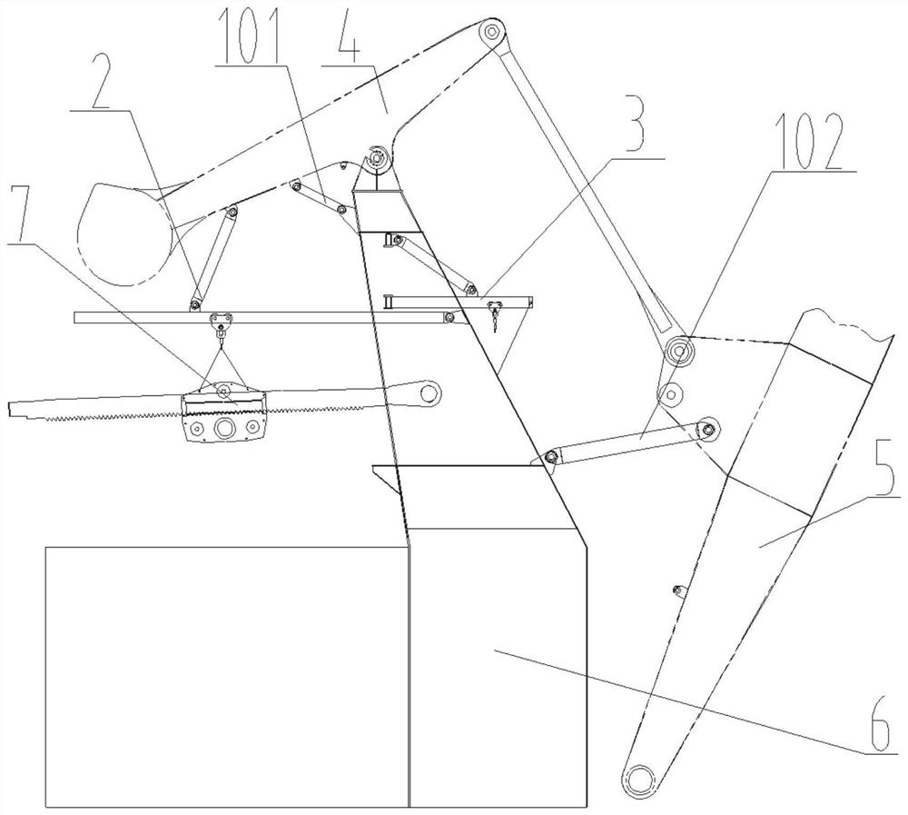
[0035] In a typical implementation of the present disclosure, such as Figure 1-Figure 6 As shown, an auxiliary device for the maintenance of the luffing mechanism is proposed.

[0036] The auxiliary device mainly includes a binding assembly, a first assembly and a second assembly. The binding assembly is used to constrain the movement of the four-link balance structure of the crane so that the four-link balance structure of the crane is in a fixed state. Through the first assembly and the second assembly Suspension maintenance hoist, wire rope, sling and other lifting maintenance tools, maintenance and transfer of parts of the dismantled luffing mechanism;

[0037] The first component is a rotating maintenance crane component, which is used for maintenance, short-distance transfer and movement of various parts of the luffing mechanism; the second component is a four-link maintenance crane component, which is used for maintenance and transfer of various parts of the luffing me...

Embodiment 2

[0082] In another typical implementation of the present disclosure, such as Figure 1-Figure 6 As shown, a working method using the auxiliary device in embodiment 1 is proposed.

[0083] Include the following steps:

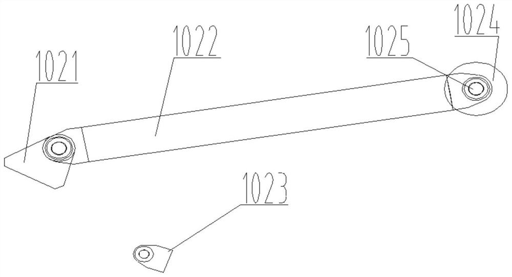
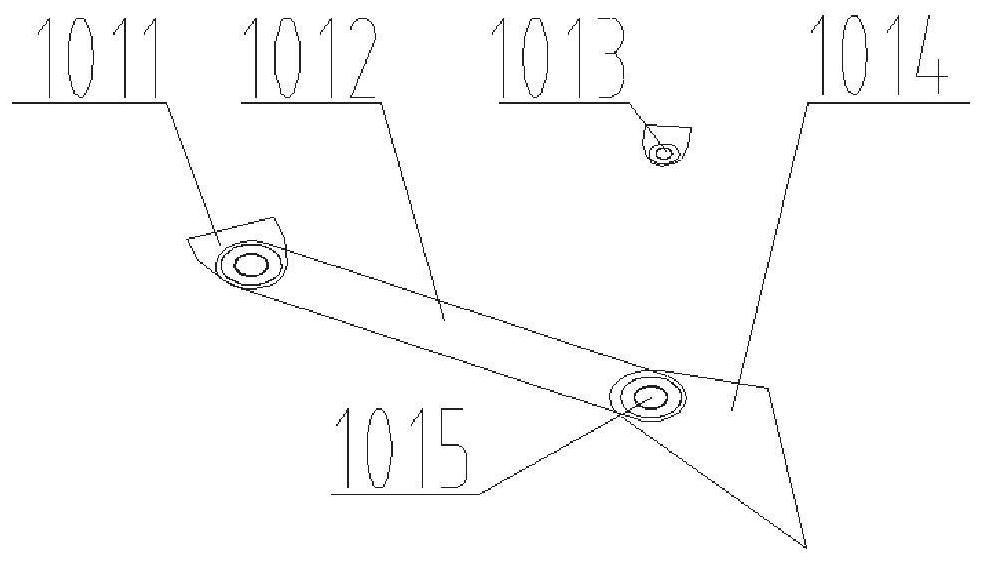
[0084]When the door machine is working normally, the front pull rod 1022 in the binding assembly 1 is fixed on the second fixing seat 1023, and swings with the arm frame 5, and the rear strut 1012 in the binding assembly 1 is fixed on the first fixing seat 1013, and moves with the balance Beam 4 swings;

[0085] The four-link maintenance crane assembly 2 forms a four-bar linkage mechanism with the balance beam 4 and the column 6, and the movable link 202 and the second slide bar 203 move with the flapping of the balance beam 4; the rotating maintenance crane assembly 3 passes through the traction chain 304 Be fixed on one side wall of column 6.

[0086] During the maintenance of the luffing mechanism, the rear strut 1012 in the strapping assembly 1 is fixed on...

Embodiment 3

[0092] In yet another typical implementation of the present disclosure, such as Figure 1-Figure 6 As shown, a portal crane is proposed, utilizing an auxiliary device for luffing mechanism maintenance as described in Example 1.

[0093] It includes the frame, the four-link balance structure of the crane and the auxiliary device for the maintenance of the luffing mechanism as described in Embodiment 1; the four-link balance structure of the crane is installed on the frame, and the auxiliary device is correspondingly installed on the four-link crane In terms of balance structure, the luffing mechanism is maintained;

[0094] The specific cooperation relationship between the crane's four-bar linkage balance structure and the auxiliary mechanism is as described in Embodiment 1, and the arrangement is made with reference to the description in Embodiment 1, and will not be repeated here.

[0095] By arranging the auxiliary device directly on the four-link balance structure of the c...


PUM


Abstract

The invention provides an auxiliary device for maintenance of a luffing mechanism and a gantry crane, and relates to the field of crane maintenance. The auxiliary device comprises a first sliding rodand a second sliding rod which are hinged to a stand column, wherein the first sliding rod matches with a first trolley moving in the axial direction of the first sliding rod, the first sliding rod horizontally rotates around a vertical line where a hinged point of the first sliding rod and the stand column is located, the second sliding rod is hinged to a balance beam through a connecting rod andused for jointly rotating in a vertical plane under the action of the balance beam, a second trolley moving in the axial direction of the second sliding rod matches with the second sliding rod, and the first trolley and the second trolley are used for cooperatively conveying luffing mechanism parts. The auxiliary device for maintaining the luffing mechanism is arranged on a four-bar linkage balance structure of the crane in advance, during maintaining, the auxiliary device binds and restrains the four-bar linkage balance structure of the crane, a four-bar linkage maintaining crane assembly and a rotary maintaining crane assembly are adopted, lifting lugs do not need to be installed and welded any more, nondestructive construction is achieved, restorative construction is not needed, and the whole maintenance efficiency is improved.

Description

technical field [0001] The disclosure relates to the field of crane maintenance, in particular to an auxiliary device for the maintenance of a luffing mechanism and a portal crane. Background technique [0002] The statements in this section merely provide background information related to the present disclosure and may not necessarily constitute prior art. [0003] The maintenance of the luffing mechanism of the portal crane is mainly completed by external equipment such as cranes, wire ropes, and supporting tooling. The maintenance process requires a lot of work such as hoisting, welding, transfer, repair, etc. The construction volume is large and the process is cumbersome and complicated. For example, dismantling the transfer rack requires the following procedures: 1. Weld the boom and the balance system through tooling, and bind them firmly; 2. Weld the lifting lugs on the top of the luffing platform, weld the lifting lugs under the balance beam, remove the rack, 3. Af...

Claims


Application Information

Patent Timeline
Patent Type & Authority Applications(China)
IPC IPC(8): B66C23/18B66C11/12
CPCB66C11/12B66C23/18
Inventor 王义凡梁强赵增林王行才周保珠
Owner QINGDAO HAIXI HEAVY DUTY MASCH CO LTD
Why Eureka
Try Eureka