One-step optical fiber cutter and optical fiber cutting method

An optical fiber and cutter technology, applied in the coupling of optical waveguides, metal processing and other directions, can solve the problems of low fiber cutting efficiency and complicated operation steps, and achieve the effects of improving cutting efficiency, simplifying cutting steps, and simple structure

Active Publication Date: 2022-02-15
BENGBU JIXIN COMM MACHINERY
View PDF9 Cites 0 Cited by
  • Summary
  • Abstract
  • Description
  • Claims
  • Application Information

AI Technical Summary

Problems solved by technology

[0003] What the present invention aims to overcome is that the existing manual optical fiber cutting tool needs to manually push the cutter to move and reset, the operation steps are cumbersome, and the problems of low optical fiber cutting efficiency are provided. The purpose is to provide a one-step optical fiber cutting tool and optical fiber cutting method

Method used


Image

  • One-step optical fiber cutter and optical fiber cutting method
  • One-step optical fiber cutter and optical fiber cutting method
  • One-step optical fiber cutter and optical fiber cutting method

Examples


Embodiment 1

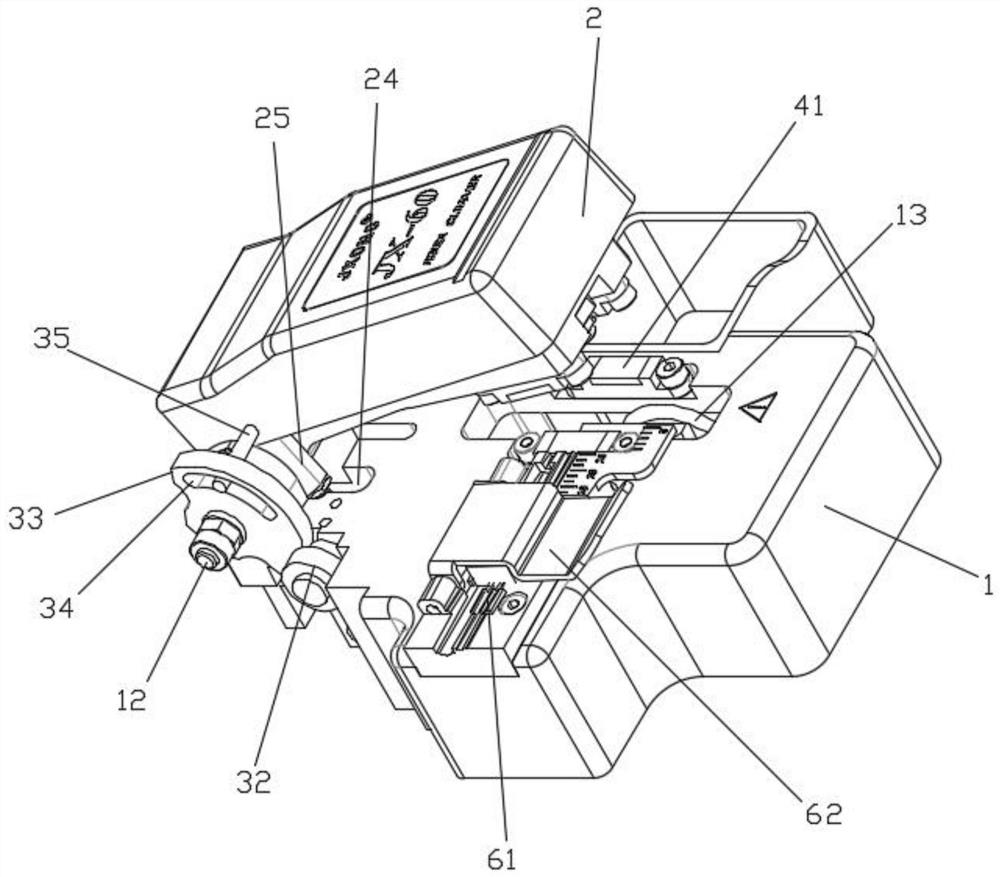
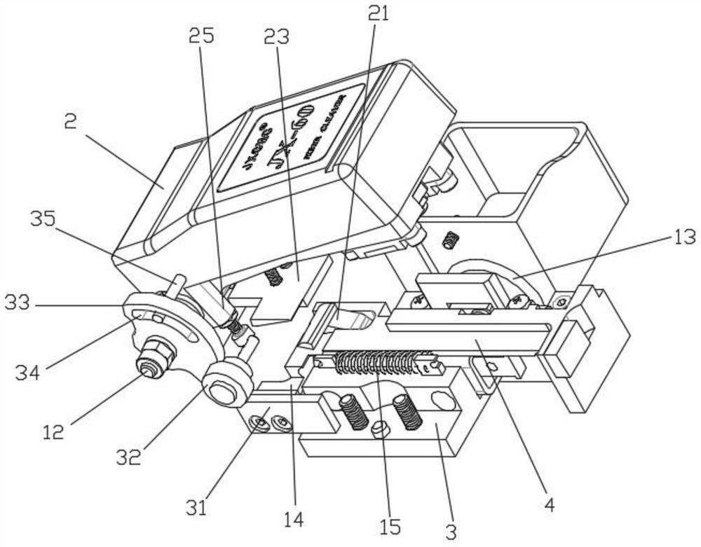
[0032] Such as figure 1 , 2 , 3, 4, and 6, a one-step optical fiber cutter, including:

[0033] Base 1, a positioning shaft 12 is fixedly installed on one side of the upper part of the base 1;

[0034] Pressing plate 2, pressing plate 2 is rotated and installed on the positioning shaft 12;

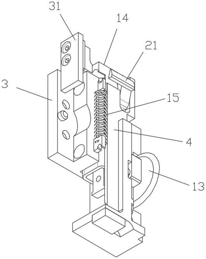
[0035] The slide rail base 3, the slide rail base 3 is fixedly installed on the base 1;

[0036] Cutting slide rail 4, and cutting slide rail 4 is slidably installed on slide rail base 3, and cutting knife 13 is installed on cutting slide rail 4, and one end of cutting slide rail 4 is provided with connecting seat 14, and connecting seat 14 and slide rail base 3 A traction spring 15 is provided between them;

[0037] The upper end surface of the connecting seat 14 is hingedly equipped with a hook 21, an extruding spring 22 is arranged between the middle part of the hook 21 and the connecting seat 14, a pinch plate 23 is provided at the bottom of the base 1, and a perforation 24 is prov...

Embodiment 2

[0041] On the basis of Example 1, such as Figure 5 , 6 As shown, the base 1 is provided with an optical fiber support seat 41, a torsion spring 42 is installed on the positioning shaft 12, and the torsion spring 42 exerts a torsion force on the pressure plate 2, and the direction of the torsion force is deflected to the side away from the base 1, and the positioning shaft 12 is rotated and installed The limiting plate 43 is provided with a through groove 44 on the limiting plate 43, and the positioning pin 45 is fixed on the pressure plate 2, and the positioning pin 45 passes through the through groove 44. The optical fiber limiting seat 46 is installed on the limiting plate 43, and the pressure plate 2 covers When being fitted on the base 1 , the optical fiber limiting seat 46 is pressed on the upper part of the optical fiber supporting seat 41 . The optical fiber is clamped by the optical fiber limiting seat 46 and the optical fiber supporting seat 41 to facilitate cutting...

Embodiment 3

[0044] On the basis of Example 1, such as Figure 7 As shown, the base 1 is provided with a wire groove 61, and a gland 62 is hingedly mounted on the side of the wire groove 61. Facilitates the positioning of the fiber on the base 1.

[0045]The base 1 is provided with a lock groove 63, and the end side of the pressure plate 2 is provided with a positioning hole 64. A lock block 65 is slidably installed in the lock groove 63. When the pressure plate 2 is covered on the base 1, the lock block 65 can be inserted into the positioning hole 64. , the inside of the positioning hole 64 and the lower end of the locking groove 63 are respectively equipped with magnets 66 . When the pressure plate 2 is covered on the base 1, the lock block 65 is inserted into the positioning hole 64 to realize the limit of the pressure plate 2, which is convenient for retracting and retracting the cutter. The magnet 66 is set, and the magnet 66 is used for adsorption to prevent the lock block. 65 off....


PUM


Abstract

The invention provides a one-step optical fiber cutter and an optical fiber cutting method, and the one-step optical fiber cutter comprises a base, a pressing plate, a sliding rail base and a cutting sliding rail, a positioning shaft is fixedly installed on one side of the upper portion of the base, the pressing plate is rotationally installed on the positioning shaft, the sliding rail base is fixedly installed on the base, the cutting sliding rail is installed on the sliding rail base in a sliding mode, a cutter is installed on the cutting sliding rail, a connecting base is arranged at one end of the cutting sliding rail, and a traction spring is arranged between the connecting base and the sliding rail base; relationship is established between deflection of the pressing plate and movement of the cutting sliding rail through a shifting rod, a sector gear, a duplicate gear and a rack, then a hook is arranged on the connecting base on the cutting sliding rail, a buckle plate is arranged on the base, the operation can be completed by pressing the pressing plate, the cutter does not need to be pushed again to move, and after cutting is completed, the cutter can be automatically driven to reset through deflection of the pressing plate, manual resetting of the cutter is not needed, the optical fiber cutting efficiency is greatly improved, and the cutting steps are simplified.

Description

technical field [0001] The invention relates to the technical field of optical fiber cutting, in particular to a one-step optical fiber cutter and an optical fiber cutting method. Background technique [0002] In the existing manual optical fiber cutters on the market, it is necessary to manually push the optical fiber cutter on the tool to move during the cutting process to realize the cutting of the optical fiber, and after the cutting is completed, the cutter needs to be reset manually, and each The steps are cumbersome and inefficient during cutting. Contents of the invention [0003] What the present invention aims to overcome is that the existing manual optical fiber cutting tool needs to manually push the cutter to move and reset, the operation steps are cumbersome, and the optical fiber cutting efficiency is low. The purpose is to provide a one-step optical fiber cutting tool and an optical fiber cutting method. [0004] Technical problem to be solved by the prese...

Claims


Application Information

Patent Timeline
Patent Type & Authority Applications(China)
IPC IPC(8): B26D5/08B26D1/18B26D7/02G02B6/25
CPCB26D5/08B26D7/02B26D1/18G02B6/25Y02P40/57
Inventor 张超田林云
Owner BENGBU JIXIN COMM MACHINERY
Why Eureka
Try Eureka