
Combined 3D printing equipment framework

A 3D printing, combined technology, applied in the direction of additive processing, etc., to achieve the effect of cheap materials, increased scalability, and convenient and rapid adjustment

Inactive Publication Date: 2022-02-15
深圳市瑞精创实业有限公司
View PDF0 Cites 0 Cited by
  • Summary
  • Abstract
  • Description
  • Claims
  • Application Information

AI Technical Summary

Problems solved by technology

[0003] The present invention provides a combined 3D printing equipment framework, which aims to solve the problem that most existing 3D printers adopt a welded and fixed framework structure for stability and airtightness.

Method used


Image

  • Combined 3D printing equipment framework
  • Combined 3D printing equipment framework
  • Combined 3D printing equipment framework

Examples


Embodiment Construction

[0028] In order to make the object, technical solution and advantages of the present invention clearer, the present invention will be further described in detail below in conjunction with the accompanying drawings and embodiments. It should be understood that the specific embodiments described here are only used to explain the present invention, not to limit the present invention.

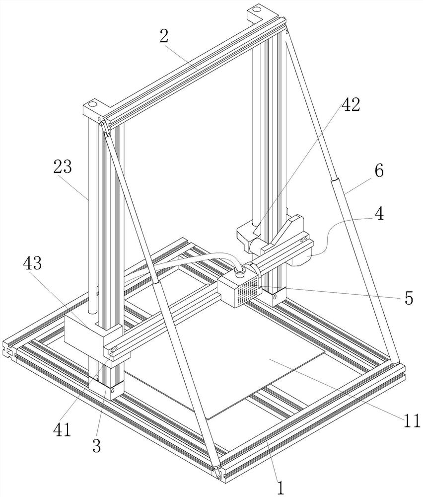
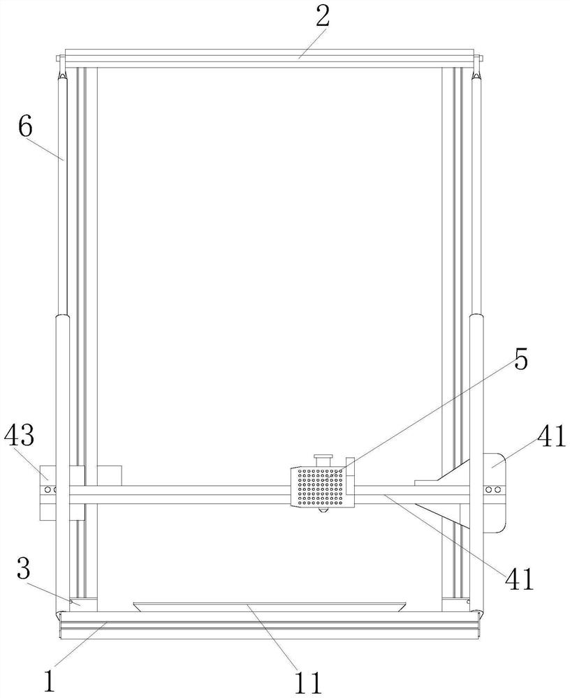
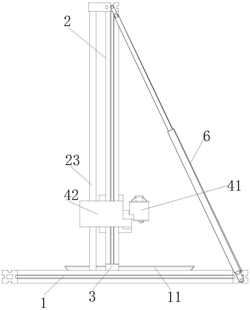
[0029] see Figure 1-6 , the present invention provides a technical solution:

[0030] A combined 3D printing equipment architecture, including a chassis 1 and a frame 2, the frame 2 and the chassis 1 are composed of aluminum alloy profiles, the bottom of the frame 2 slides and locks on the chassis 1 through the connecting seat 3, and the bottom of the frame 2 A liftable printing bar 4 is installed, and a hot-melt printing head 5 is slidably arranged on the printing bar 4, wherein: the connecting seat 3 is locked on the bottom frame 1 when the frame 2 is pressed down, and is locked on the bottom f...


PUM


Abstract

The invention is suitable for the technical field of 3D printing equipment, and provides a combined 3D printing equipment framework which comprises a bottom frame and a frame. The frame and the bottom frame are both formed by splicing aluminum alloy sections, the bottom of the frame slides and is locked on the bottom frame through a connecting base, a liftable printing cross rod is installed on the frame, a hot melting printing head is arranged on the printing cross rod in a sliding mode, and the connecting base is locked on the bottom frame when the frame is pressed downwards and moves on the bottom frame when the frame is lifted upwards. The bottom frame, the frame and the printing cross rod are all made of aluminum alloy sections, on one hand, materials are convenient and cheap, so that the manufacturing cost is low, on the other hand, the aluminum alloy sections are welded or screwed, the process difficulty in the whole manufacturing process is low, and the whole machining and assembling speed is high, simple and easy to operate; and due to the overall outward opening type, assembly line type machining is facilitated.

Description

technical field [0001] The invention belongs to the technical field of 3D printing equipment, and in particular relates to a combined 3D printing equipment architecture. Background technique [0002] At present, the frames of 3D printers are mostly rectangular cuboid structures, and there are openings on the sides of the cuboids to observe and take printed objects. In order to ensure stability and airtightness, most of this type of 3D printers adopt a welded and fixed frame structure. It is extremely inconvenient for debuggable and mobile printing objects. Its space is limited and its structure is heavy. With the development of 3D printing, the demand for prototypes emerges in an endless stream. This fixed and closed 3D printer obviously cannot meet the demand. Contents of the invention [0003] The present invention provides a combined 3D printing equipment framework, aiming at solving the problem that most of the existing 3D printers adopt a welded and fixed framework st...

Claims


Application Information

Patent Timeline
Patent Type & Authority Applications(China)
IPC IPC(8): B29C64/20B33Y30/00
CPCB29C64/20B33Y30/00
Inventor 罗文瀚张硕龙天正梁志楚
Owner 深圳市瑞精创实业有限公司
Learn More