Paperboard cutting device for packaging box production and processing
A cutting device and packaging box technology, applied in packaging, transportation and packaging, paper/cardboard containers, etc., can solve the problems of time-consuming and labor-intensive work, large labor input, etc., and achieve the effect of improving work efficiency and facilitating packaging and processing
- Summary
- Abstract
- Description
- Claims
- Application Information
AI Technical Summary
Problems solved by technology
Method used
Image

Examples
Embodiment 1
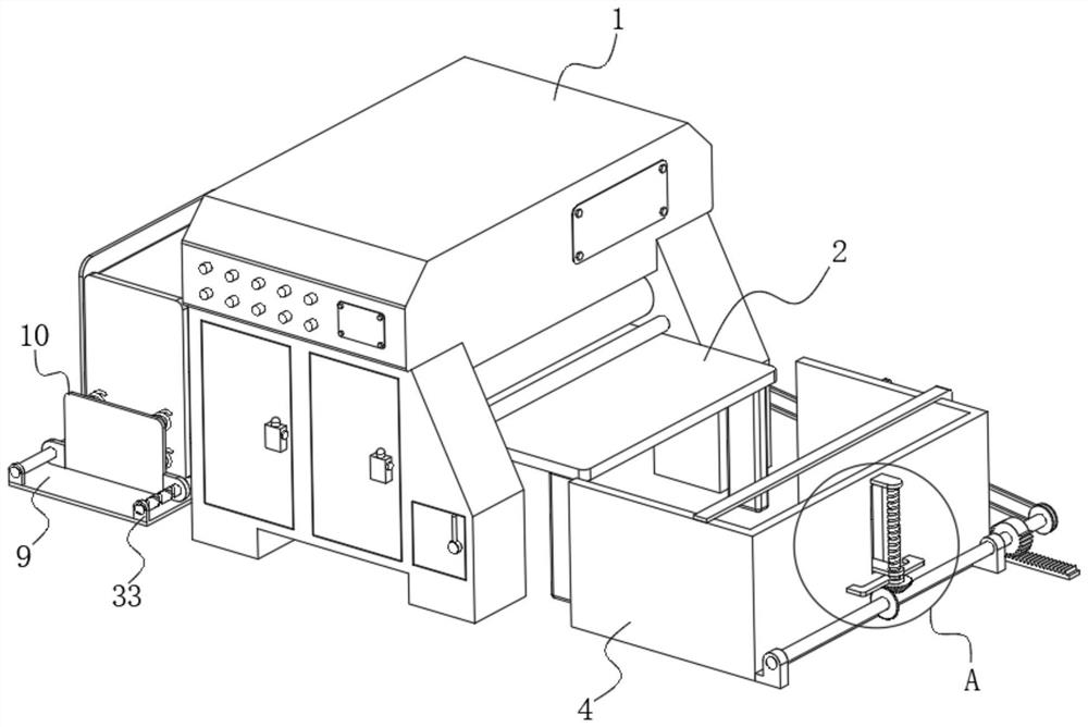
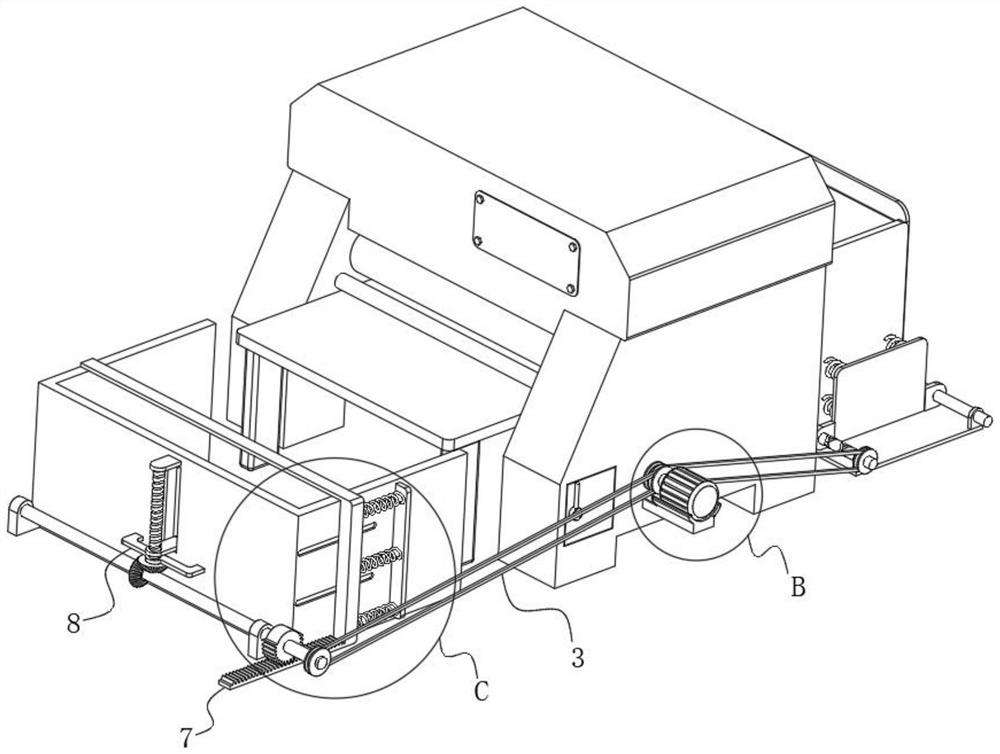
[0027] see Figure 1-Figure 9 , the present invention provides a technical solution: a cardboard cutting device for packaging box production and processing, including: a cutting machine 1, a conveying table 2 is arranged in the cutting machine 1; a driving assembly 3, and the driving assembly 3 is arranged on the cutting machine 1; The placement frame 4 arranged at the delivery end of the conveying table 2 has a communication groove 5 on the placement frame 4, and a plurality of sets of sliding grooves 6 are provided on one side, and a push assembly connected with the driving assembly 3 is connected through the plurality of sets of sliding grooves 6 7; lifting assembly 8, the lifting assembly 8 is arranged on the placement frame 4 and connected with the communication groove 5; the collection frame 9 arranged at the collection end of the conveying table 2, the collection frame 9 is provided with a finishing assembly 10 connected with the drive assembly 3 .
[0028] see Figur...
Embodiment 2
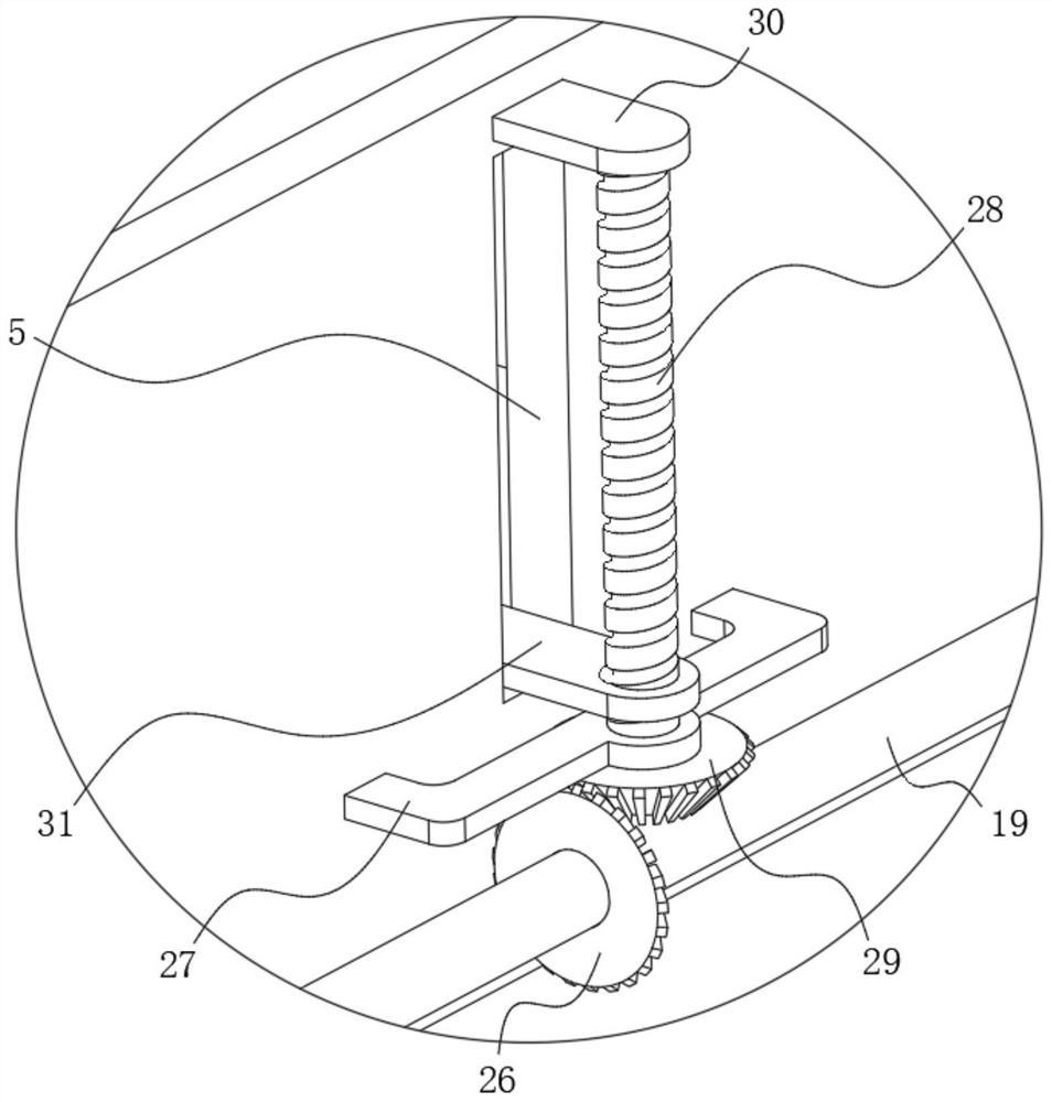
[0033] refer to figure 1 , figure 2 and Figure 8 Illustrate embodiment 2, this embodiment will further illustrate embodiment 1, and lifting assembly 8 comprises the first bevel gear 26 that is arranged on the rotating shaft 19 and is fixedly connected with it, and the placement frame 4 is fixedly connected with the first bevel gear that is arranged on the first bevel gear. The connecting frame 27 above the 26, the connecting frame 27 is rotatably connected with a threaded rod 28, one end of the threaded rod 28 is fixedly connected with the second bevel gear 29 meshed with the first bevel gear 26, and the other end is rotatably connected with the placement frame 4 The connecting block 30 that is fixedly connected is threadedly connected with a lifting block 31 that is slidably connected with the communication groove 5, and the lifting block 31 is fixedly connected with a lifting plate 32 that is slidably connected with the inner wall of the placement frame 4, wherein, in ord...
Embodiment 3
[0036] refer to Figure 6 , Figure 7 and Figure 9 Illustrate embodiment 3, this embodiment is described further to embodiment 1, finishing assembly 10 comprises the first mounting block 33 and the second mounting block 34 that multiple groups are arranged on the collecting rack 9 and are fixedly connected with it, multiple groups of first mounting blocks 34 Two groups of reciprocating screw mandrels 35 that are fixedly connected to each other are rotatably connected between the blocks 33. Two groups of reciprocating screw mandrels 35 are mirror images, and one set of reciprocating screw mandrels 35 is fixedly connected with the second driven wheel 17. Multiple sets of second mounting blocks 34 is fixedly connected with fixed shaft 36, two groups of reciprocating screw rods 35 are all threaded with mobile plate 37 that is slidably connected with fixed shaft 36, and collection frame 9 is fixedly connected with collection seat 38, and there are many groups of The limiting gro...
PUM
 Abstract
Description
Claims
Application Information
PatSnap Eureka turns technology decisions into work you can execute. Powered by our Innovation Knowledge Graph, it runs expert workflows across engineering, life sciences, materials and intellectual property. Get your review-ready output in minutes.


