
Electrified railway double-current system traction power supply system and control method thereof

A technology for traction power supply systems and electrified railways, applied to electrical components, power lines, and individual AC networks with different frequencies, etc., can solve problems such as the complexity of transportation networks, achieve the effects of improving utilization effects, reducing construction area and costs

Active Publication Date: 2022-02-15
SOUTHWEST JIAOTONG UNIV
View PDF7 Cites 7 Cited by
  • Summary
  • Abstract
  • Description
  • Claims
  • Application Information

AI Technical Summary

Problems solved by technology

[0003] With the development and construction of rail transit, the transportation network is intricate, and it is inevitable that some places will have the coexistence of AC traction power supply system and DC traction power supply system. The traditional single power supply system can no longer meet the needs of dual-current system power supply. It can be used in the traction transition section between AC electric traction vehicles and DC urban rail vehicles; moreover, the locomotives of different voltage levels and current systems produced by China's rolling stock manufacturers also need different traction power supply systems to provide power for debugging and testing, and build a double-stream Control the traction power supply system, so that it can supply power to both AC electric traction vehicles and DC urban rail vehicles, so as to make the operation as efficient and economical as possible, to reduce redundant construction as much as possible, and to avoid huge waste of resources. Therefore It is necessary to study the dual-current traction power supply scheme

Method used


Image

  • Electrified railway double-current system traction power supply system and control method thereof
  • Electrified railway double-current system traction power supply system and control method thereof
  • Electrified railway double-current system traction power supply system and control method thereof

Examples


Embodiment 1

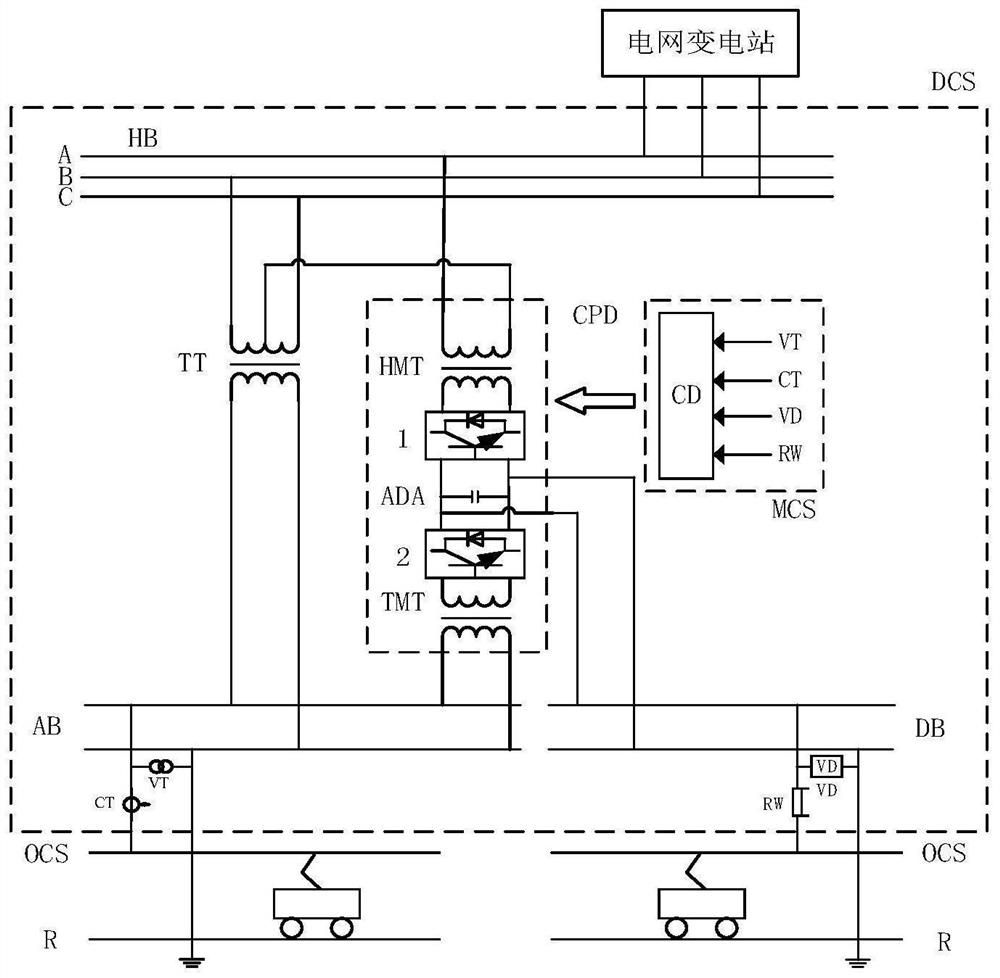
[0029] like figure 1 As shown, the embodiment of the present invention provides a dual-current traction power supply system for electrified railways. Two terminals of the primary side of the traction transformer TT are connected to any two phases of the three-phase high-voltage bus HB, and the secondary side is connected to the AC On the bus AB; the same-phase compensation device CPD includes a high-voltage matching transformer HMT, an AC-DC converter ADA, and a traction matching transformer TMT; the primary side of the high-voltage matching transformer HMT is connected to the three-phase high-voltage bus HB, so that the secondary winding of the traction transformer TT and The voltage phase difference of the secondary winding of the high-voltage matching transformer HMT is 90°, the traction matching transformer TMT is connected with the AC bus AB, the DC side of the AC-DC-AC converter ADA is parallel connected with the DC bus DB; one end of the AC bus AB is connected in series ...

Embodiment 2

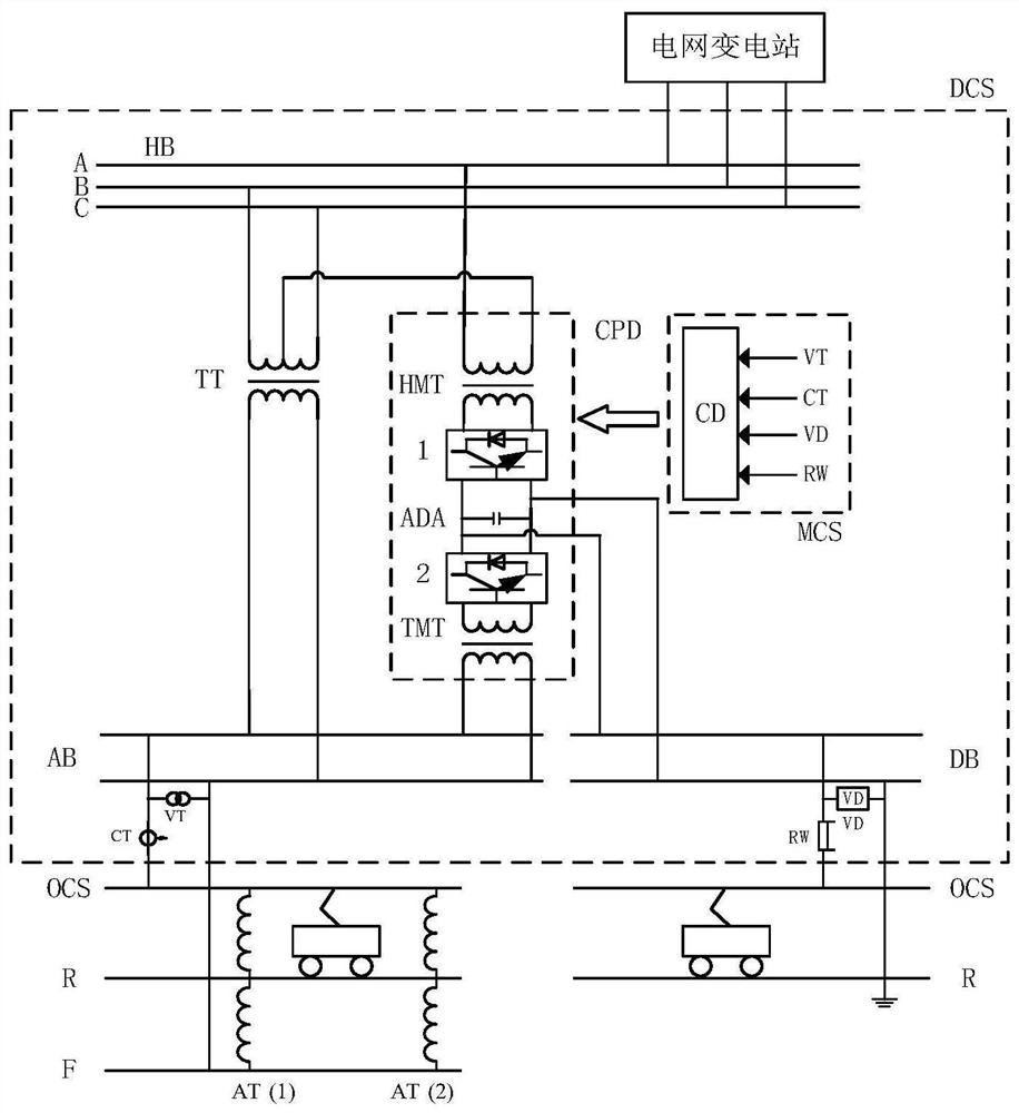
[0032] like Figure 4 As shown, the embodiment of the present invention provides a dual-current traction power supply system for electrified railways. The primary side of the traction transformer TT is connected to any two phases of the three-phase high-voltage bus HB, and the primary side of the high-voltage matching transformer HMT is connected to the three-phase high-voltage bus HB is connected so that the voltage phase difference between the secondary winding of the traction transformer TT and the secondary winding of the high-voltage matching transformer HMT is 90°; TT constitutes a balanced connection, in which the secondary winding of the traction transformer TT and the secondary winding of the high-voltage matching transformer HMT form a 90° voltage phase difference.

Embodiment 3

[0034] like Figure 5 As shown, the present invention provides a schematic flow chart of a method for controlling electric railway dual-stream traction power supply, and the specific steps are:

[0035] (1) Set the compensation target as the negative-sequence allowable amount S of the three-phase high-voltage bus HB ε ;

[0036] (2) Calculate the measured voltage and current values ​​through the controller CD of the comprehensive compensation measurement and control system MCS, and calculate the AC load power S L1 and DC load power S L2 , to obtain the maximum AC negative sequence power generated by the AC load power and DC load power passing through any channel of the traction transformer or high-voltage matching transformer and DC maximum negative sequence power And judge its relationship with the three-phase high-voltage bus negative-sequence allowable S ε relationship; if or and At this time, there is no need to compensate the negative sequence; if and At ...


PUM


Abstract

The invention discloses an electrified railway double-current system traction power supply system and a control method thereof, and relates to the technical field of electrified railway power supply. The electrified railway double-current system traction power supply system comprises a three-phase high-voltage bus HB, a traction transformer TT, an in-phase compensation device CPD, an alternating-current bus AB, a direct-current bus DB and a measurement and control system MCS which are arranged in the double-current traction substation DCS. The secondary side of the traction transformer TT is connected to an alternating current bus AB in parallel, and the direct current side of the alternating current-direct current-alternating current converter ADA is connected to a direct current bus DB in parallel, so that required power is provided for a train, and alternating current and direct current power supply at the same place is realized; the measurement and control system MCS is composed of a voltage transformer VT, a voltage transmitter VD, a current transformer CT, a diverter RW and a controller CD and can calculate alternating current load power and direct current load power, the generated negative sequence power is compared with the three-phase high-voltage bus negative sequence allowable quantity, the output power of a converter is controlled in real time, the negative sequence generated by an electrified railway is compensated, and the compensated negative sequence meets the compensation target requirement.

Description

technical field [0001] The invention relates to the technical field of electrified railway traction power supply, in particular to a dual-stream traction power supply system and control method for electrified railway. Background technique [0002] At present, the AC traction power supply system in my country's rail transit adopts 27.5kV or 55kV power frequency single-phase AC power supply, and the DC traction power supply system generally adopts 1500V or 750V DC power supply. Due to the different power supply systems, the two traction power supply systems generally use their own independent single system power supply. [0003] With the development and construction of rail transit, the traffic network is intricate, and it is inevitable that some places will have the coexistence of AC traction power supply system and DC traction power supply system. The traditional single power supply system can no longer meet the needs of dual-current system power supply. It can be used in th...

Claims


Application Information

Patent Timeline
IPC IPC(8): B60M3/00H02J3/02H02J5/00
CPCB60M3/00H02J3/02H02J5/00Y02E40/50
Inventor 解绍锋黄大锐刘骆川李群湛吴波易东郭锴黄小红张丽艳张丽
Owner SOUTHWEST JIAOTONG UNIV
Learn More