Supercharge Your Innovation With Domain-Expert AI Agents!

Double-impeller combined self-suction mixed-flow pump

A dual-impeller, mixed-flow pump technology, which is applied to the components, pumps, driving pumps, etc. of the pumping device for elastic fluid, can solve the problems of inconvenient connection of water pipes, low water-lifting efficiency of mixed-flow pumps, etc., and improve water-lifting efficiency. , the effect of simple and convenient connection

Pending Publication Date: 2022-02-15
扬州市瑞峰泵业制造有限公司
View PDF0 Cites 0 Cited by
  • Summary
  • Abstract
  • Description
  • Claims
  • Application Information

AI Technical Summary

Problems solved by technology

[0003] In order to solve the problems of low water-lifting efficiency of the above-mentioned mixed-flow pump and inconvenient connection of water pipes, and achieve the purpose of high water-lifting efficiency of the above-mentioned mixed-flow pump and convenient connection of water pipes, the present invention achieves the following technical solutions: a combination of double impellers A self-priming mixed-flow pump includes a pump body, a water inlet pipe arranged at the bottom of the pump body, and an outlet pipe arranged at the top of the pump body. A mixed-flow chamber is provided on the inner surface of the pump body, and a first impeller, the inner surface of the mixed flow chamber is provided with a second impeller, the top of the mixed flow chamber is provided with a drain port, the top of the pump body is provided with an additional block, and the inner surface of the additional block is provided with a confluence groove, so The outer surface of the water inlet pipe is provided with a sealing plug, the outer surface of the water inlet pipe is rotatably connected with a rotating shell, the inner surface of the rotating shell is provided with an air storage cavity, and the inner surface of the rotating shell is provided with an air guide groove, The inner surface of the rotating shell is provided with a movable chamber, the inner surface of the movable chamber is slidably connected with a fixed cone, and the outer surface of the water inlet pipe is provided with auxiliary parts

Method used


Image

  • Double-impeller combined self-suction mixed-flow pump
  • Double-impeller combined self-suction mixed-flow pump
  • Double-impeller combined self-suction mixed-flow pump

Examples


Embodiment Construction

[0018] Next, the technical solutions in the embodiments of the present invention will be described in connection with the drawings of the embodiments of the present invention, and it is understood that the described embodiments are merely the embodiments of the present invention, not all of the embodiments. Based on the embodiments of the present invention, all other embodiments obtained by those of ordinary skill in the art are in the range of the present invention without making creative labor premise.

[0019] The double impeller combined self-suction flow pump is implemented, for example:

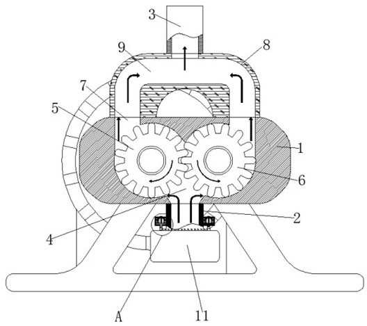
[0020] See figure 1 - Figure 4 A double-blade combination self-suction flow pump, including the pump body 1, the water pump body 2 provided at the bottom of the pump body 1 and the water pipe 3 disposed at the top of the pump body 1, the inner side of the pump body 1 is opened, and there is a mixed flow chamber 4, The inner side surface of the mixing chamber 4 is provided with the inner sid...


PUM


Abstract

The invention discloses a double-impeller combined self-suction mixed-flow pump, which comprises a pump body, a water inlet pipe arranged at the bottom of the pump body and a water outlet pipe arranged at the top of the pump body, a mixed-flow chamber is formed in the inner side face of the pump body, a first impeller is arranged on the inner side face of the mixed-flow chamber, a second impeller is arranged on the inner side face of the mixed-flow chamber, a water outlet is formed in the top of the mixed-flow chamber, an additional block is arranged on the top of the pump body, a confluence groove is formed in the inner side face of the additional block, a sealing plug is arranged on the outer surface of the water inlet pipe, and a rotating shell is rotationally connected to the outer surface of the water inlet pipe; the first impeller and the second impeller are matched with each other, so that the suction force in the mixed-flow chamber is increased, the entered fluid can enter the confluence groove from the two sides of the mixed-flow chamber, the flow of the mixed-flow pump is greatly increased, the water lifting amount is increased when the impellers rotate by a circle, and the water lifting efficiency of the mixed-flow pump can be effectively improved.

Description

Technical field [0001] The present invention relates to the field of mixed flow pumps, in particular a double-blade combination self-suction flow pump. Background technique [0002] The mixed flow pump is a pump between the centrifugal pump and the axial flow pump. The mixed flow pump is higher than the centrifugal pump, which is lower than the axial flow pump, typically between 300-500. Its tightening is high than the axial flow, but the flow rate is small, larger than the centrifugal pump. When the original motif is rotating, the effect of the liquid has both centrifugal force and axial thrust, and is a synthesis of centrifugal pump and axial flow pump. The existing mixed flow pump is low in water, although its water absorption speed can be faster, but can only be achieved by adjusting the speed of the motor, so the water feed speed is fast, but its actual The water water is still low, thereby causing waste of energy, which is not conducive to the practice of energy conservatio...

Claims


Application Information

Patent Timeline
Patent Type & Authority Applications(China)
IPC IPC(8): F04D9/02F04D29/18F04D29/40F04D29/60
CPCF04D9/02F04D29/185F04D29/406F04D29/605
Inventor 吴敏
Owner 扬州市瑞峰泵业制造有限公司
Features
  • R&D
  • Intellectual Property
  • Life Sciences
  • Materials
  • Tech Scout
  • Unparalleled Data Quality
  • Higher Quality Content
  • 60% Fewer Hallucinations
Learn More