Porous flow guide type power blade for hydraulic torque converter

A technology for hydraulic torque converters and blades, applied in fluid transmission devices, transmission devices, hydroelectric power generation, etc., can solve the problems of small contact area, short contact time, and reduced service life of blades, so as to increase the contact area and improve the use of The effect of life and work efficiency improvement

Active Publication Date: 2022-02-15
JILIN UNIV
View PDF5 Cites 0 Cited by
  • Summary
  • Abstract
  • Description
  • Claims
  • Application Information

AI Technical Summary

Problems solved by technology

[0002] The working principle of the hydraulic torque converter is: the hydraulic torque converter is composed of the pump wheel turbine and the guide wheel. There is transmission oil in the hydraulic torque converter. After starting the engine, the pump wheel will rotate, so that the transmission oil will From the guide wheel to the wheel, the guide wheel will also rotate under the action of the transmission oil. The pump wheel is connected to the flywheel of the engine, and the turbine is connected to the power input shaft of the gearbox. The guide wheel is sandwiched between the pump wheel and the turbine wheel, and the pump wheel and There is a special structural design on the turbine, so that the transmission oil can be used to transmit power. The hydraulic torque converter is composed of a pump wheel, a turbine, and a guide wheel. It is installed between the engine and the transmission, and the hydraulic oil ( ATF) is the working medium, which plays the role of torque transmission, torque conversion, speed change and clutch, while the impeller is the core of the hydraulic torque converter, its type, arrangement position and blade shape determine the performance of the torque converter Function, the traditional rectangular power blades have a short contact time with the transmission oil during use, and the contact area is small, resulting in a lot of hydraulic loss, and the faster the impeller rotates, the more hydraulic loss, and when the speed changes When the tank oil is driven by centrifugal force, the transmission oil will leave the power blades. At this time, the blades are not cooled by the transmission oil, and the temperature will rise rapidly, increasing the loss of the blades and reducing the service life of the blades. In view of this, here is a proposal A porous guide type power blade for hydraulic torque converter to solve the above problems

Method used


Image

  • Porous flow guide type power blade for hydraulic torque converter
  • Porous flow guide type power blade for hydraulic torque converter
  • Porous flow guide type power blade for hydraulic torque converter

Examples


Embodiment Construction

[0024] The following will clearly and completely describe the technical solutions in the embodiments of the present invention with reference to the accompanying drawings in the embodiments of the present invention. Obviously, the described embodiments are only some, not all, embodiments of the present invention.

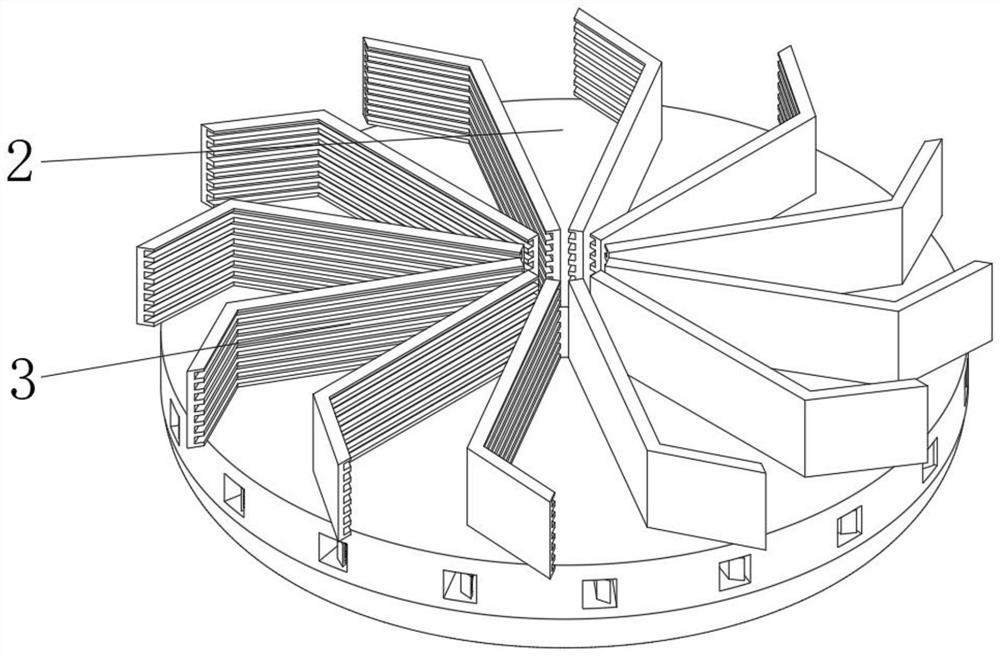
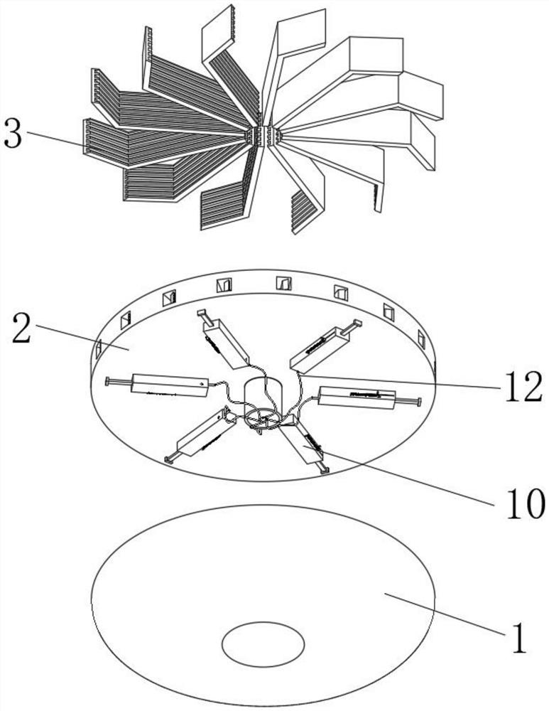
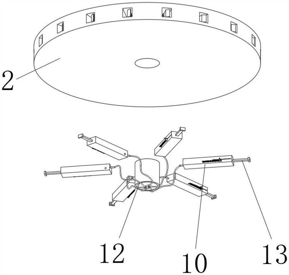
[0025] see figure 1 , figure 2 , image 3 , Figure 4 and Figure 5 , the present invention provides a technical solution: a porous guide type power blade for a hydraulic torque converter, including a casing 1, a driving disc 2 is installed on the inner side of the casing 1, and a power blade is fixedly installed on the surface of the driving disc 2 3. The shape of the power blade 3 is bent, and the inside of the power blade 3 is provided with a driving groove, which can effectively avoid the problem that the transmission oil is easy to separate from the power blade 3. Using the driving groove inside the power blade 3 can increase The contact area between the ge...


PUM


Abstract

The invention discloses a porous flow guide type power blade for a hydraulic torque converter, and relates to the technical field of power blades, in particular to the porous flow guide type power blade for the hydraulic torque converter, which comprises a shell, a driving disc is mounted on the inner side of the shell, and power blades are fixedly mounted on the surface of the driving disc. Mounting grooves are formed in the peripheries of the interiors of the power blades. According to the porous flow guide type power blade for the hydraulic torque converter, through the bending shape of the power blade, when the power blade makes contact with gearbox oil, the gearbox oil can be blocked through the bending position of the power blade, and the problem that the gearbox oil is prone to being separated from the power blade can be effectively solved; by means of the driving grooves formed in the power blades, the contact area between gearbox oil and the power blades can be increased, so that hydraulic loss can be effectively reduced, and the working efficiency of the power blades is improved.

Description

technical field [0001] The invention relates to the technical field of power blades, in particular to a porous guide type power blade used in a hydraulic torque converter. Background technique [0002] The working principle of the hydraulic torque converter is: the hydraulic torque converter is composed of the pump wheel turbine and the guide wheel. There is transmission oil in the hydraulic torque converter. After starting the engine, the pump wheel will rotate, so that the transmission oil will From the guide wheel to the wheel, the guide wheel will also rotate under the action of the transmission oil. The pump wheel is connected to the flywheel of the engine, and the turbine is connected to the power input shaft of the gearbox. The guide wheel is sandwiched between the pump wheel and the turbine wheel, and the pump wheel and There is a special structural design on the turbine, so that the transmission oil can be used to transmit power. The hydraulic torque converter is co...

Claims


Application Information

Patent Timeline
Patent Type & Authority Applications(China)
IPC IPC(8): F16H41/26F16H41/30
CPCF16H41/26F16H41/30Y02E10/20
Inventor 刘春宝杨孔华熊佳伟唐钰骁
Owner JILIN UNIV
Why Eureka
Try Eureka