Multi-input turn-off device, control method and photovoltaic power generation system
A multi-input, disconnector technology, used in photovoltaic power generation, photovoltaic modules, electrical components, etc., can solve the problems of high cost and large number of diodes, and achieve the effect of improving efficiency, reducing heat generation, and reducing bypass loss.
- Summary
- Abstract
- Description
- Claims
- Application Information
AI Technical Summary
Problems solved by technology
Method used
Image

Examples
Embodiment Construction
[0038] The present invention will be described in detail below in conjunction with the specific embodiments shown in the accompanying drawings, but these embodiments do not limit the present invention, those skilled in the art make structural, method, or functional changes based on these embodiments All are included in the scope of protection of the present invention.
[0039]When an element is referred to as being "connected to" or "coupled to" another element, the element may be directly on, connected to, or coupled to the other element, or intervening elements may be present. . However, when an element is referred to as being "directly connected to" or "directly coupled to" another element, there are no intervening elements present. To this end, the term "connected" may refer to a physical connection, an electrical connection, etc., with or without intervening components.
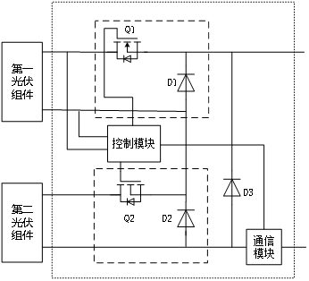
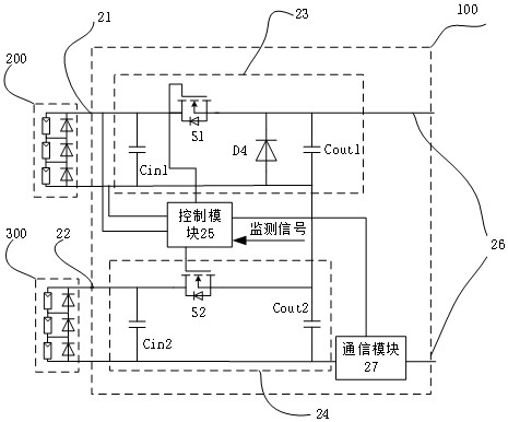
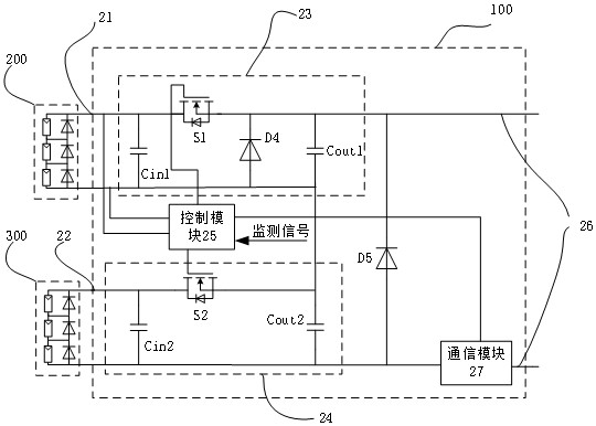
[0040] figure 2 It is a schematic circuit structure diagram of the multi-input switch according t...
PUM
 Abstract
Description
Claims
Application Information
PatSnap Eureka turns technology decisions into work you can execute. Powered by our Innovation Knowledge Graph, it runs expert workflows across engineering, life sciences, materials and intellectual property. Get your review-ready output in minutes.


