
Column foot bifurcated type combination column with reduced anchoring depth

A technology of combining columns and column bases, applied in the directions of columns, piers, pillars, etc., can solve the problems of increased equipment costs, labor costs, large excavation depths of foundation pits, and increased construction periods, so as to enhance the embedded effect and reduce comprehensive Cost and effect of reducing excavation depth

Pending Publication Date: 2022-02-18
南通欧本建筑科技有限公司
View PDF5 Cites 0 Cited by
  • Summary
  • Abstract
  • Description
  • Claims
  • Application Information

AI Technical Summary

Problems solved by technology

[0002] The traditional steel column is a closed composite component, which is embedded or outsourced to the foundation. The general embedment depth is 2-3 times the outer diameter of the component; for example, a circular tubular concrete column with a diameter of 800mm needs to be embedded at a depth of 2.4 meters. ;In the traditional closed composite member, the column does not open fork, and the concrete column is inserted into the concrete, which has a "crowbar" effect, and the bending and pulling resistance can only be realized by increasing the anchorage depth; thus resulting in a large foundation pit excavation depth, The equipment cost and labor cost used are greatly increased, and the construction period is also increased

Method used


Image

  • Column foot bifurcated type combination column with reduced anchoring depth
  • Column foot bifurcated type combination column with reduced anchoring depth
  • Column foot bifurcated type combination column with reduced anchoring depth

Examples


Embodiment Construction

[0019] In order to make the purpose, technical solution and advantages of the present invention clearer, the technical solution of the present invention will be further described below.

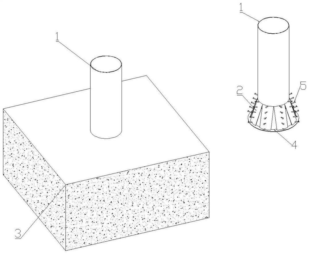
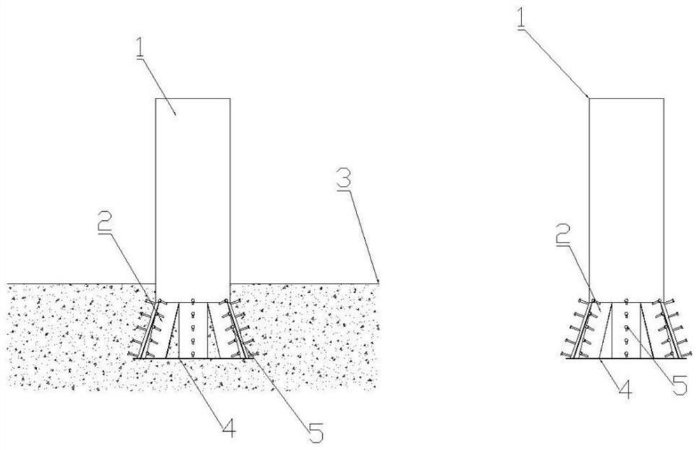
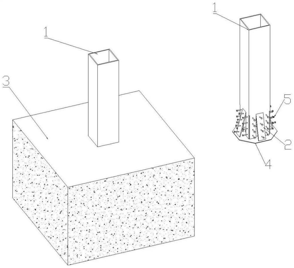
[0020] The present invention proposes a combination column with split foot for reducing the anchorage depth. The combined column is a split foot combination column 1; the column foot of the combined column 1 is cut upward from the bottom of the column foot to cut out multiple pieces of anchorage. Plate 2; the bottom of each anchor plate 2 is bifurcated towards the outside of the column, forming a scattered tree root structure; the gap generated by the bifurcation of the anchor plate 2 is used to connect the concrete inside the tube and the concrete outside the tube of the combined column 1; bifurcated The reinforced version does not increase the steel consumption of the original composite column 1, and the overall steel cost does not increase, but it is similar to the structure of the tree roo...


PUM


Abstract

The invention provides a column foot bifurcated type combination column with a reduced anchoring depth, wherein a column foot of the combination column is cut upwards from the bottom of the column foot, and a plurality of anchoring plates are cut out; the bottom of each anchoring plate is bifurcated towards the outside of the column to form a dispersed tree root structure; a gap generated by forking of the anchor plate is used for connecting concrete inside the combined column pipe and concrete outside the combined column pipe into a whole, the whole steel using area of the steel column is not changed, and the built-in effect between the steel column and a foundation is effectively enhanced by designing the forked column foot; the hole is formed in the column foot of the combination column, so that concrete inside the pipe and concrete outside the pipe are connected into a whole, the anchoring end plate is additionally arranged at the bottom, and the anchoring depth of the steel column can be greatly reduced on the premise that the built-in effect is guaranteed; the foundation pit excavation depth is reduced, the comprehensive cost is reduced, and the construction period is shortened. The column feet of the combination column are directly stressed, secondary stress conversion is avoided, and force transmission is reliable and high in efficiency; and when necessary, studs can be additionally welded on the embedded part of the anchoring plate, so that the embedding and fixing effect with the foundation is further enhanced.

Description

technical field [0001] The invention relates to the technical field of construction, in particular to a split-type composite column with a reduced anchorage depth. Background technique [0002] The traditional steel column is a closed composite component, which is embedded or outsourced to the foundation. The general embedment depth is 2-3 times the outer diameter of the component; for example, a circular tubular concrete column with a diameter of 800mm needs to be embedded at a depth of 2.4 meters. ;In the traditional closed composite member, the column does not open fork, and the concrete column is inserted into the concrete, which has a "crowbar" effect, and the bending and pulling resistance can only be realized by increasing the anchorage depth; thus resulting in a large foundation pit excavation depth, The equipment cost and labor cost used are greatly increased, and the construction period is also increased. Contents of the invention [0003] The purpose of the pre...

Claims


Application Information

Patent Timeline
Patent Type & Authority Applications(China)
IPC IPC(8): E04C3/34E04B1/58E02D27/42E02D27/50E04B1/41
CPCE04C3/34E04B1/58E02D27/42E02D27/50E04B1/41
Inventor 陈明李云鹏
Owner 南通欧本建筑科技有限公司
Learn More