Steel pipe pile steel trestle end and its construction method

A construction method and technology of steel pipe piles, applied in bridges, sheet pile walls, bridge materials, etc., can solve the problems of poor soil connectivity, inconvenient driving construction, and different bearing capacity, so as to improve the wave resistance and Effects of lateral soil pressure, smooth sailing to embankment, and increased bearing capacity

Active Publication Date: 2021-05-28
湖北省路桥集团有限公司
View PDF0 Cites 0 Cited by
  • Summary
  • Abstract
  • Description
  • Claims
  • Application Information

AI Technical Summary

Problems solved by technology

[0002] At present, as a temporary structure, the steel trestle construction platform is in a harsh environment and is greatly affected by the environment. Especially for rivers with high flow rates, the design of the steel trestle construction platform considers many loads, such as : Water flow force, wave force, drilling rig load, transportation machinery, overweight machinery, cargo stacking, etc., these factors will have an important impact on the steel trestle bridge, and the following diseases are prone to occur: 1) The bridge end of the steel trestle bridge and the abutment overlap due to The bearing capacity is different, and there is a jumping phenomenon, which leads to the inconvenience of driving and construction
2) The steel pipe piles are located on the shore, and are vulnerable to the erosion of water flow and the displacement of lateral earth pressure, resulting in poor connection between the steel pipe piles and the surrounding soil, large displacement of the pile body, and poor bearing capacity

Method used


Image

  • Steel pipe pile steel trestle end and its construction method
  • Steel pipe pile steel trestle end and its construction method
  • Steel pipe pile steel trestle end and its construction method

Examples


Embodiment Construction

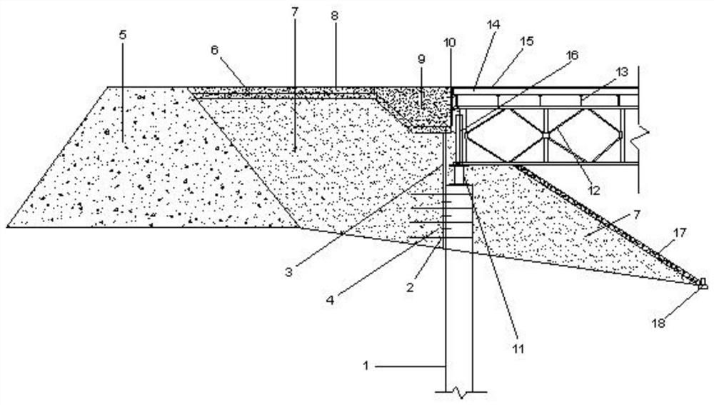
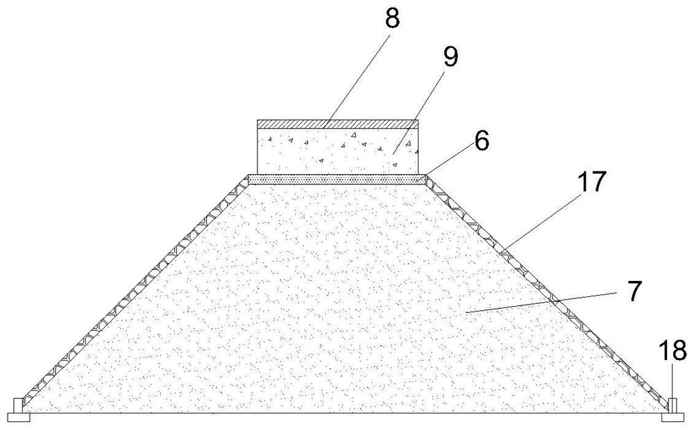
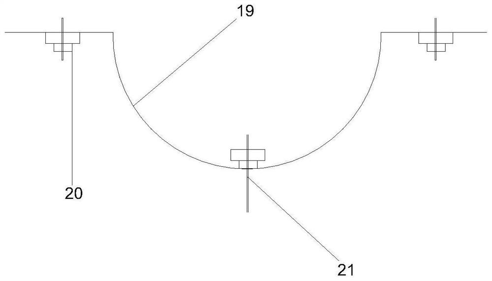
[0035] The following will clearly and completely describe the technical solutions in the embodiments of the present invention with reference to the accompanying drawings in the embodiments of the present invention. Obviously, the described embodiments are only some, not all, embodiments of the present invention. Based on the embodiments of the present invention, all other embodiments obtained by persons of ordinary skill in the art without creative efforts fall within the protection scope of the present invention.

[0036] In describing the present invention, it is to be understood that the terms "opening", "upper", "lower", "thickness", "top", "middle", "length", "inner", "surrounding" etc. Indicating orientation or positional relationship is only for the convenience of describing the present invention and simplifying the description, and does not indicate or imply that the components or elements referred to must have a specific orientation, be constructed and operated in a sp...


PUM


Abstract

The invention discloses a steel trestle end of a steel pipe pile and a construction method thereof, belonging to the technical field of bridge construction. The invention includes steel pipe piles, slag baffles, embankments, concrete slabs, Bailey girders, reinforced poles, etc. The steel pipe piles are equipped with vertical bar partitions, and the steel pipe piles are welded at the limit end. The partition plate with size matching notch is put into the rotation limit, and the partition plate is evenly arranged in the circumferential direction with casing anchor cables, and the micro-expansion concrete is poured into the pipe piles, and the tension of the anchor cables exerts prestress on the core-filled steel pipe piles; Horizontal reinforcements are set around the pipe piles to reduce the lateral earth pressure and deformation of the steel pipe piles, and concrete laps are set for lap transition to reduce the impact of the steel trestle on the embankment. The invention increases the bearing capacity of the pile foundation through the steel pipe pile, and the steel pipe pile and the slag gravel are well embedded, so that the pile foundation is stable with the house, and the service life of the bridge end is guaranteed to be improved.

Description

technical field [0001] The invention belongs to the technical field of bridge construction, in particular to a construction method for steel trestle ends of steel pipe piles. Background technique [0002] At present, as a temporary structure, the steel trestle construction platform is in a harsh environment and is greatly affected by the environment. Especially for rivers with high flow rates, the design of the steel trestle construction platform considers many loads, such as : Water flow force, wave force, drilling rig load, transportation machinery, overweight machinery, cargo stacking, etc., these factors will have an important impact on the steel trestle bridge, and the following diseases are prone to occur: 1) The bridge end of the steel trestle bridge and the abutment overlap due to Due to the difference in bearing capacity, jumping occurs, which makes driving and construction inconvenient. 2) Steel pipe piles are located on the shore, and are vulnerable to erosion by...

Claims


Application Information

Patent Timeline
Patent Type & Authority Patents(China)
IPC IPC(8): E01D19/02E01D21/00E02D5/38E02D27/32E01D101/30
CPCE01D19/02E01D21/00E01D2101/30E02D5/38E02D27/32E02D2300/002E02D2300/0029E02D2600/20
Inventor 李高磊吴惠君何振华赵君秦海涛
Owner 湖北省路桥集团有限公司
Why Eureka
Try Eureka