
Non-contact photographing hole-measuring calibration device and method

A non-contact, calibration device technology, applied in the direction of measuring devices, optical devices, instruments, etc., can solve the problems of hole position calculation errors, inability to judge hole accuracy, and inability to satisfy accurate hole measurement, etc., to improve position accuracy , The effect of ensuring position accuracy

Active Publication Date: 2022-02-18
CHENGDU AIRCRAFT INDUSTRY GROUP
View PDF15 Cites 2 Cited by
  • Summary
  • Abstract
  • Description
  • Claims
  • Application Information

AI Technical Summary

Problems solved by technology

[0005] The above-mentioned prior art proposes a calibration method of a binocular stereo vision measurement system in a CNC machine tool, which is used for positional relationship conversion of point cloud data after the spatial position relationship between the CNC machine tool coordinate system and the measurement coordinate system is established. However, when using this method to measure holes by photography, it can only ensure that the hole is within the camera’s photographing area, and the position accuracy of the hole cannot be judged. Moreover, if the edge contour of the hole is photographed in a non-normal direction, the hole contour will appear elliptical. The contour of the hole is distorted, which leads to the wrong calculation of the hole position, which cannot meet the needs of accurate hole measurement

Method used


Image

  • Non-contact photographing hole-measuring calibration device and method
  • Non-contact photographing hole-measuring calibration device and method
  • Non-contact photographing hole-measuring calibration device and method

Examples


Embodiment 1

[0058] At present, there are mainly two types of measuring instruments and measurement methods for the position of holes on skin parts: (1) three-coordinate measuring machine contact measurement; (2) non-contact photographic hole measurement method.

[0059] For the first measurement method, when the measurement scheme has hundreds of group holes attached to large skin parts, the detection time is long, and it is difficult to meet the requirements of high efficiency of production cycle, while the second measurement method has image Identification, data processing, rapid detection and other advantages, so it is becoming the focus of research and the next development direction.

[0060] However, when the existing non-contact photographic hole measuring method is in use, the main body and object of measurement during actual measurement are still holes, which leads to the photographing of the edge profile of the hole in a non-normal direction, and the hole profile will appear ellip...

Embodiment 2

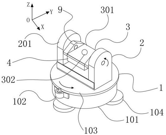
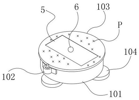
[0068] This embodiment discloses a non-contact photographic hole measuring device. figure 1 - attached Figure 6 , on the basis of Embodiment 1, this embodiment makes further limitations on the calibration device, specifically as follows.

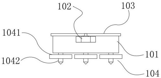
[0069] The base 1 also includes a fine-tuning unit 104, the fine-tuning unit 104 is provided on the lower surface of the base body 101, and the number of the fine-tuning units 104 is three, which are evenly distributed on the lower surface of the base body 101 for adjusting the flatness of the base 1; The fine-tuning unit 104 is an integrated nut and screw structure, including an integrally formed anti-skid nut 1041 and a screw rod 1042, the anti-skid nut 1041 is fixedly sleeved on the screw rod 1042, the diameter of the front and rear sections of the screw rod 1042 is 10mm, and one side of the end is conical. The other end is an M8*10 thread, and the surface of the anti-skid nut 1041 is provided with staggered scratches for anti-skid, the...

Embodiment 3

[0081] Based on the same inventive concept, this embodiment provides a non-contact photoborehole calibration method, which is realized by the non-contact photoborehole calibration device in the above embodiment, and the method specifically includes the following steps:

[0082] Step S101. Leveling the overall reference of the calibration device.


PUM


Abstract

The invention relates to the technical field of image measurement calibration, and discloses a non-contact photographing hole-measuring calibration device and method, the device comprises a base, a mounting platform, a calibration assembly and an illumination compensator, the mounting platform is arranged on the base, and the calibration assembly is arranged on the mounting platform; in the calibration process, the base drives the mounting platform to rotate around the Z axis so as to drive the calibration assembly to rotate around the Z axis, the mounting platform drives the calibration assembly to rotate around the X axis at the same time, the illumination compensator is used for supplementing light for the camera in the camera photographing process, and the camera system analyzes and calculates the obtained images of the calibration spherical circle contour projection. Therefore, the calibration of the connecting hole is finally realized. According to the invention, the traditional photographing hole measurement calibration is innovatively converted into the photographing hole measurement calibration ball for calibration, so that the problem that the hole is possibly distorted into an ellipse at different angles during the traditional photographing hole measurement calibration is well solved, and the calibration precision is improved.

Description

technical field [0001] The invention relates to the field of machine vision, in particular to the technical field of image measurement and calibration, in particular to a non-contact camera hole measurement calibration device and method. Background technique [0002] In aircraft assembly, the composite skin and the metal structural parts inside the aircraft are first assembled together through positioning holes. Affected by the assembly of the aircraft skeleton, the skin needs to be repaired on the skeleton to meet the installation requirements of the skin. Use a portable drill to make a large number of connection holes on the skin, and then perform spot-sinking on the connection holes with a CNC machine tool. Finally, workers use pneumatic tools to drive rivets into the spot-sink holes, finally achieving a reliable connection between the skin and the metal structure. [0003] Since the position of each connecting hole in the machining coordinate system must be accurately kn...

Claims


Application Information

Patent Timeline
Patent Type & Authority Applications(China)
IPC IPC(8): G01B11/00G01B21/04
CPCG01B11/002G01B21/042
Inventor 牟文平蒋云峰黄明聪姜振喜李卫东张桂李博沈昕
Owner CHENGDU AIRCRAFT INDUSTRY GROUP
Learn More