Pressure sensor

A pressure sensor and pressure technology, applied in the direction of pressure sensor, sensor, measuring fluid pressure, etc., can solve the problems of large diameter, unable to meet medical needs, no dead zone, and unsatisfactory, and achieve the effect of reducing the diameter

Pending Publication Date: 2022-02-18
MEASUREMENT SPECIALTIES CHINA
View PDF0 Cites 0 Cited by
  • Summary
  • Abstract
  • Description
  • Claims
  • Application Information

AI Technical Summary

Problems solved by technology

Since the horizontally installed circuit board extends in the radial direction of the oil-filled pressure sensor, the diameter of the entire oil-filled pressure sensor is relatively large, usually greater than 6.9mm, which cannot meet the requirements of the demanding sensor for human implantation
In addition, in the prior art, oil-filled pressure sensors all contain diaphragm welding rings, which will form a flow dead zone for the pressure transmission medium, which cannot meet the requirement of no dead zone in the medical industry

Method used


Image

  • Pressure sensor
  • Pressure sensor
  • Pressure sensor

Examples


no. 1 example

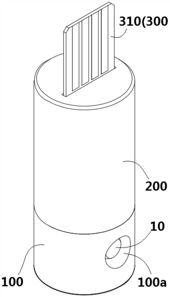
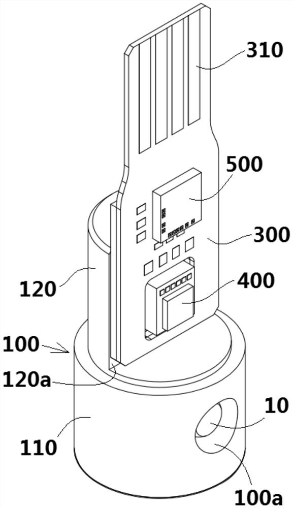
[0043] Figure 1 to Figure 4 A pressure sensor according to a first embodiment of the invention is shown. in, figure 1 A three-dimensional schematic diagram showing a pressure sensor according to the first embodiment of the present invention; figure 2 show figure 1The pressure sensor shown with the housing 200 removed; image 3 show figure 2 A three-dimensional schematic view of the pressure sensor shown when viewed from the rear; Figure 4 show figure 1 Cutaway view of the pressure sensor shown.

[0044] Such as Figure 1 to Figure 4 , in the illustrated embodiment, the pressure sensor mainly includes: a body 100 , a diaphragm 600 , a pressure detection chip 400 and a circuit board 300 . A housing chamber for housing liquid is formed inside the body 100 . The diaphragm 600 is attached to the body 100 and is adapted to transmit the pressure of the external medium to the liquid in the chamber. The pressure detection chip 400 is mounted on the body 100 for detecting ...

no. 2 example

[0069] Figure 5 and Figure 6 A pressure sensor according to a second embodiment of the invention is shown. in, Figure 5 A schematic perspective view showing a pressure sensor according to a second embodiment of the present invention, wherein the housing 200 is removed; Figure 6 A cross-sectional view of a pressure sensor according to a second embodiment of the present invention is shown.

[0070] Figure 5 and Figure 6 The second embodiment shown with Figure 1 to Figure 4 The main difference of the first shown embodiment is the location of the liquid filling port 110a and the positioning groove.

[0071] Such as Figure 5 and Figure 6 As shown, in the illustrated embodiment, the liquid filling port 110 a is formed on the top surface of the installation part 120 and directly communicates with the upper end of the trunk passage 101 .

[0072] Such as Figure 5 and Figure 6 As shown, in the illustrated embodiment, a circular positioning groove 100b and a bar-sh...

no. 3 example

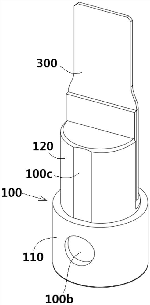
[0075] Figure 7 and Figure 8 A pressure sensor according to a third embodiment of the invention is shown. in, Figure 7 A schematic perspective view showing a pressure sensor according to a third embodiment of the present invention, wherein the housing 200 is removed; Figure 8 A sectional view showing a pressure sensor according to a third embodiment of the present invention;

[0076] Figure 7 and Figure 8 The third embodiment shown with Figure 1 to Figure 4 The main difference of the first shown embodiment is the location of the liquid filling port 110a and the positioning groove.

[0077] Such as Figure 7 and Figure 8 As shown, in the illustrated embodiment, the liquid filling port 110a is formed on the peripheral surface of the installation part 120 on the side opposite to the installation surface 120a.

[0078] Such as Figure 7 and Figure 8 As shown, in the illustrated embodiment, a bar-shaped positioning groove 100c extending in the axial direction th...


PUM

PropertyMeasurementUnit
diameteraaaaaaaaaa

Abstract

The invention discloses a pressure sensor comprising a body, a diaphragm, a pressure detection chip and a circuit board; an accommodating cavity for accommodating liquid is formed in the body; the diaphragm is attached to the body and is suitable for transmitting pressure of an external medium to the liquid in the accommodating cavity; the pressure detection chip is mounted on the body and is used for detecting the pressure of the liquid in the accommodating cavity; and the circuit board is arranged on the body and is electrically connected with the pressure detection chip, a flat mounting surface is formed on the body, the mounting surface extends along the axial direction of the body, and the pressure detection chip and the circuit board are arranged on the mounting surface. According to the pressure sensor, the circuit board is vertically mounted on the mounting surface extending in the axial direction, so that the radial size of the pressure sensor cannot be increased by the circuit board, the diameter of the pressure sensor can be reduced, and the pressure sensor can be implanted into a human body.

Description

technical field [0001] The invention relates to a pressure sensor. Background technique [0002] An oil-filled pressure sensor usually includes a metal case, a detection diaphragm, a detection chip and a circuit board. In the prior art, an oil cavity extending axially is formed in the metal casing, and the detection chip and the circuit board are installed horizontally on the top of the metal casing. Since the horizontally installed circuit board extends in the radial direction of the oil-filled pressure sensor, the diameter of the entire oil-filled pressure sensor is relatively large, usually greater than 6.9mm, which cannot meet the requirements of the demanding sensor for human implantation. In addition, in the prior art, oil-filled pressure sensors all contain diaphragm welding rings, which will form a flow dead zone for the pressure transmission medium, which cannot meet the requirement of no dead zone in the medical industry. Contents of the invention [0003] The ...

Claims


Application Information

Patent Timeline
Patent Type & Authority Applications(China)
IPC IPC(8): G01L7/08G01L19/14A61B5/03A61B5/0215
CPCG01L7/08G01L19/14A61B5/03A61B5/0215A61B5/6846A61B2562/0247G01L19/0069G01L19/147G01L19/148G01L19/0084G01L19/0046
Inventor 张亚祥付廷辉梁许
Owner MEASUREMENT SPECIALTIES CHINA
Why Eureka
Try Eureka