Vehicle speed control method and device

A vehicle speed and control device technology, applied in the direction of measuring devices, vehicle testing, testing electrical devices in transportation, etc., can solve problems such as power consumption errors, complex technical solutions, and test failures, so as to avoid test errors and save tests Working hours, to achieve the effect of a simple solution

Pending Publication Date: 2022-02-18
DONGFENG HONDA AUTOMOBILE CO LTD
View PDF11 Cites 0 Cited by
  • Summary
  • Abstract
  • Description
  • Claims
  • Application Information

AI Technical Summary

Problems solved by technology

[0002] According to the national standard "GBT 19753-2013 Test Method for Energy Consumption of Light-duty Hybrid Electric Vehicles", when plug-in hybrid electric vehicles are tested for fuel consumption according to the test method, multiple discharges are required at a speed of 50km / h±2km / h To complete the test; at present, some plug-in hybrid models need to perform 3-4h constant-rate discharge treatment at a speed of 50km / h±2km / h to complete the test. Models using the constant speed cruise function are currently tested by manual driving to keep the car at a constant speed of 50km / h±2km / h. Manual driving control has a certain speed fluctuation deviation, which is prone to power consumption errors, resulting in power consumption and Inaccurate calculation of fuel consumption results leads to poor repeatability of test results and even test failure
[0003] The utility model patent automobile accelerator pedal experimental device with the publication number CN210863109U does not use manual labor, but completely uses the experimental device to simulate the driver's control of the accelerator pedal to keep the car running at a constant speed. The experimental device uses a drive motor and requires additional development. A computing software including an input module, a storage module, a computing module, and a drive module. This technical solution needs to increase investment in motors, software personnel and software technology development, which is not only costly but also complicated.

Method used


Image

  • Vehicle speed control method and device
  • Vehicle speed control method and device

Examples


Embodiment Construction

[0026] In order to make the purpose, technical solution and advantages of the invention clearer, the invention will be further elaborated below in conjunction with the accompanying drawings.

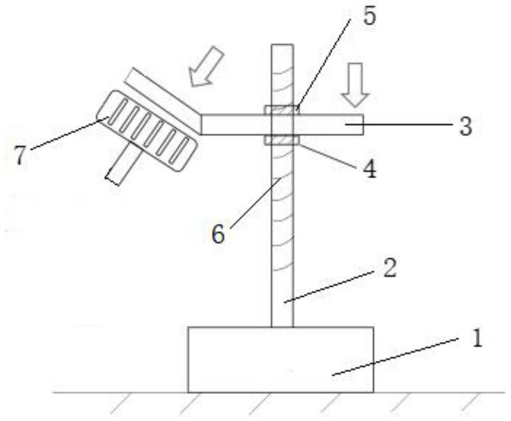
[0027] Such as figure 1 As shown, the vehicle speed control device includes a base, a support rod 2, a pressure plate 3, and a fixing device; the base is a counterweight 1, the counterweight 1 is a counterweight metal block, and the fixing device is a first nut 4 and a second nut 5. The counterweight 1 is placed on the ground of the car cab, the support rod 2 is placed vertically, and the counterweight 1 is connected as a whole with the support rod 2 as the base of the support rod 2.

[0028] Pressing plate 3 comprises pedal contact portion and connecting portion, and the pedal contacting portion of pressing plate 3 and connecting portion are one and pedal contacting portion and connecting portion are square, and the pedal contacting portion of pressing plate 3 and connecting portion for...


PUM


Abstract

The invention discloses a vehicle speed control method and device, a driver starts a vehicle and then pedals an accelerator to increase the vehicle speed to a specified vehicle speed, the feet of the driver are moved away, the vehicle speed control device is placed in a corresponding accelerator pedal position, and a pressing plate pedal contact part of the vehicle speed control device presses the accelerator pedal; a pressing plate moves up and down along a supporting rod of the vehicle speed control device, an instrument panel is observed, and when the vehicle speed reaches the designated speed, the pressing plate of the vehicle speed control device and the supporting rod are fixed through a fixing device; the pressing plate pressing the accelerator pedal is fixed through the supporting rod and the fixing device, constant-speed running of a vehicle at a specified speed in the experiment process is achieved through a manual combination device, test errors caused by manual vehicle speed control are avoided, and the technical scheme is simple and easy to achieve.

Description

technical field [0001] The invention relates to the technical field of automobile testing, in particular to a vehicle speed control method and device used in automobile testing. Background technique [0002] According to the national standard "GBT 19753-2013 Test Method for Energy Consumption of Light-duty Hybrid Electric Vehicles", when plug-in hybrid electric vehicles are tested for fuel consumption according to the test method, multiple discharges are required at a speed of 50km / h±2km / h To complete the test; at present, some plug-in hybrid models need to perform 3-4h constant-rate discharge treatment at a speed of 50km / h±2km / h to complete the test. Models using the constant speed cruise function are currently tested by manual driving to keep the car at a constant speed of 50km / h±2km / h. Manual driving control has a certain speed fluctuation deviation, which is prone to power consumption errors, resulting in power consumption and Inaccurate calculation of fuel consumption ...

Claims


Application Information

Patent Timeline
Patent Type & Authority Applications(China)
IPC IPC(8): G01M17/007G01R31/00
CPCG01M17/007G01R31/006
Inventor 刘畅邓家轩万为
Owner DONGFENG HONDA AUTOMOBILE CO LTD
Why Eureka
Try Eureka