Electromagnetic ultrasonic stress detection device for oil and gas pipeline and detection method thereof

An electromagnetic ultrasonic, oil and gas pipeline technology, applied in measuring devices, using stable tension/pressure to test the strength of materials, instruments, etc., can solve the problems of inaccurate measurement accuracy of pipeline flaw detection and great influence on accuracy, and achieve assembly time. Reduce, improve accuracy, improve assembly efficiency

Pending Publication Date: 2022-02-18
PIPECHINA SOUTH CHINA CO +1
View PDF0 Cites 0 Cited by
  • Summary
  • Abstract
  • Description
  • Claims
  • Application Information

AI Technical Summary

Problems solved by technology

[0004] The above-mentioned existing technical solutions have the following defects: the piezoelectric ultrasonic method needs a couplant to measure the residual stress, and the couplant has a great influence on the accuracy of the test results, which leads to the problem of inaccurate measurement accuracy of pipeline flaw detection

Method used


Image

  • Electromagnetic ultrasonic stress detection device for oil and gas pipeline and detection method thereof
  • Electromagnetic ultrasonic stress detection device for oil and gas pipeline and detection method thereof
  • Electromagnetic ultrasonic stress detection device for oil and gas pipeline and detection method thereof

Examples


Embodiment 1

[0028] The present invention will be described in further detail below in conjunction with the accompanying drawings.

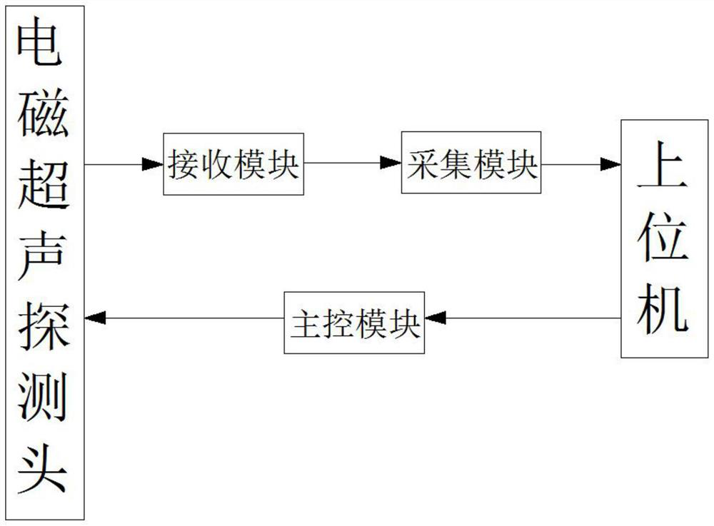
[0029] refer to figure 1 , the present invention provides an electromagnetic ultrasonic stress detection device for oil and gas pipelines, comprising an electromagnetic ultrasonic probe, the magnetic ultrasonic probe is electrically connected to a receiving module for receiving signals, the receiving module is electrically connected to an acquisition module, and the acquisition module is electrically Connect the upper computer, the upper computer is electrically connected to the main control module, the main control module is electrically connected to the electromagnetic ultrasonic probe, the upper computer is connected to the acquisition module and the main control module through the USB cable, and the signal acquisition and the control of the main control module are completed respectively Function: the acquisition module collects the amplified signal from t...

Embodiment 2

[0037] A detection method for an electromagnetic ultrasonic stress detection device for oil and gas pipelines, the method includes the following steps:

[0038] S01. Calibration oil pipeline processing and residual stress removal treatment:

[0039] The material of the oil pipeline is X65 pipeline steel, and the stretching direction of the oil pipeline is divided into axial direction and circumferential direction. Residual stress treatment adopts annealing stress relief process.

[0040]S02. When measuring sound in tensile test:

[0041] The electromagnetic ultrasonic probe is adsorbed on the calibrated part of the oil pipeline, and the pulling force is applied in a step-by-step manner to measure the sound time value under each pulling state.

[0042] S03, into the equation to solve the acoustic elastic parameters:

[0043] According to the structure of the equation, the unknown parameters in the equation are obtained by means of data fitting.

[0044] S04. Error analysis:...


PUM


Abstract

The invention discloses an electromagnetic ultrasonic stress detection device for an oil and gas pipeline, which relates to the field of industrial nondestructive testing, and aims to solve the problem that traditional pipeline flaw detection is inaccurate. The electromagnetic ultrasonic stress detection device is characterized by comprising an electromagnetic ultrasonic probe for detecting the pipeline, and the electromagnetic ultrasonic probe is electrically connected with a receiving module for receiving signals; the receiving module is electrically connected with an acquisition module, the acquisition module is electrically connected with an upper computer, the upper computer is electrically connected with a main control module, and the main control module is electrically connected with an electromagnetic ultrasonic probe. The measurement accuracy of pipeline flaw detection is improved.

Description

technical field [0001] The invention relates to the technical field of industrial nondestructive testing, in particular to an electromagnetic ultrasonic stress testing device for oil and gas pipelines. Background technique [0002] Oil and gas pipelines are the lifeline of transporting oil and natural gas. However, stress concentration is very easy to occur during the operation of the pipeline. When the stress exceeds the yield limit of the material, it will cause plastic deformation or cracks, which seriously threatens the safe operation of the pipeline. Therefore, effective detection of pipelines is a necessary measure to avoid safety accidents and improve pipeline integrity management. During the service period of pipelines, timely detection and evaluation of the stress state of pipelines will help the safe maintenance of pipelines. [0003] Among the existing ultrasonic stress measurement technologies, piezoelectric ultrasonic stress detection technology and electromagne...

Claims


Application Information

Patent Timeline
Patent Type & Authority Applications(China)
IPC IPC(8): G01N3/08G01N3/06
CPCG01N3/08G01N3/06G01N2203/0017G01N2203/0676G01N2203/0617G01N2203/0658
Inventor 吴明畅王磊磊韩昌柴王多才李洪烈李建君舒亮刘爽郭磊刘翼明连勋李智文刘勇郑贤英汪开灿夏宗亮许霁
Owner PIPECHINA SOUTH CHINA CO
Why Eureka
Try Eureka