
Temperature heating instrument for gas conveying pipeline of thermogravimetric analyzer

A thermogravimetric analyzer and gas pipeline technology, which is applied in the direction of thermal analysis of materials, analytical materials, preparation of samples for testing, etc. Reduce the possibility of clogging the trachea, reduce heat loss, and have a significant thermal insulation effect

Pending Publication Date: 2022-02-18
ANHUI UNIV OF SCI & TECH
View PDF0 Cites 0 Cited by
  • Summary
  • Abstract
  • Description
  • Claims
  • Application Information

AI Technical Summary

Problems solved by technology

The entire instrument needs to be tested in a high temperature state, and the temperature in the gas delivery hose is lower than the temperature in the instrument. After the gas in the instrument is blown out, it condenses and accumulates in the gas delivery hose, causing the mouth of the gas delivery hose to be blocked.
Existing gas hoses do not have heat insulation materials, and cannot keep the gas at a relative temperature for a long time, so as to reduce the pollution and blockage caused by gas condensation
The blockage of the pipeline will also increase the maintenance cost of the instrument, reduce the service life of the instrument, and may even cause some experimental data to deviate, resulting in the inability to obtain real results from the experiment.
At different stages of the experiment, the temperature range required for the experiment is not the same, and the existing insulation materials cannot independently adjust the temperature to ensure that the temperatures of the experimental instruments match each other

Method used


Image

  • Temperature heating instrument for gas conveying pipeline of thermogravimetric analyzer
  • Temperature heating instrument for gas conveying pipeline of thermogravimetric analyzer
  • Temperature heating instrument for gas conveying pipeline of thermogravimetric analyzer

Examples


Embodiment Construction

[0021] Specific implementation plan

[0022] DETAILED DESCRIPTION OF THE PREFERRED EMBODIMENT OF THE INVENTION OF THE INVENTION OF THE INVENTION OF THE INVENTION The following examples are described below in connection with the accompanying drawings. Based on the embodiments in the present invention, there are all other embodiments obtained without making creative labor premises, in the preceding embodiments of the present invention.

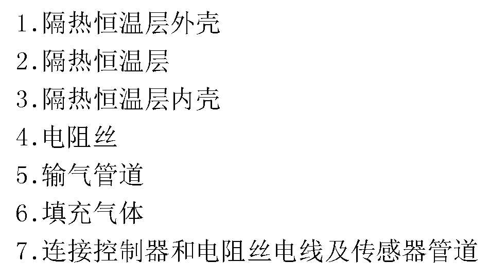
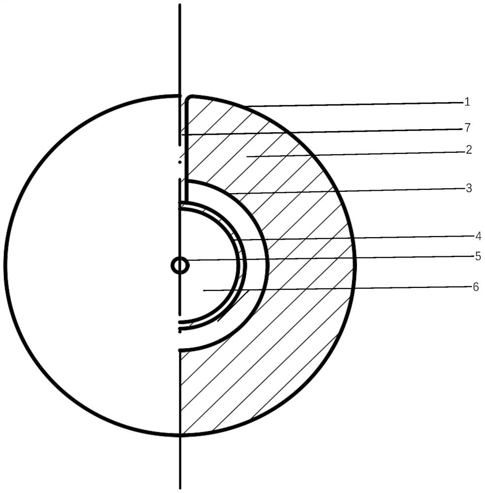
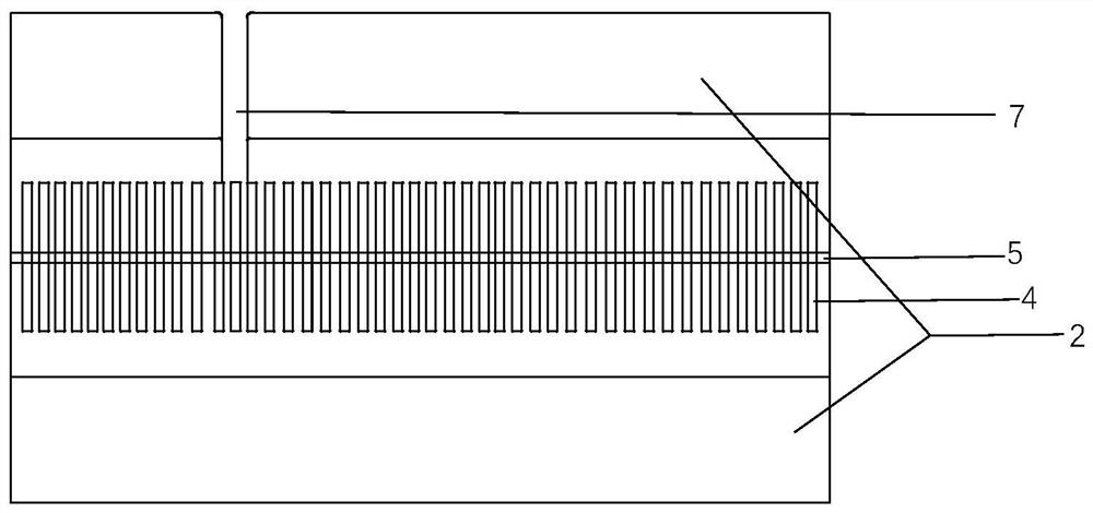
[0023] like figure 1 and 2 As shown, the present invention provides a resistor wire to the gas barrel, and the heating of the controller is controlled. The heat insulating thermal layer includes an aluminum outer casing and an inner casing that performs high vacuum treatment therefrom, sealing treatment in the pipe start end and the end, only the air supply soft tube can be left. The connection resistance wire is applied to the control terminal to protect the heat insulating layer to ensure the sealing of the insulation layer. Gas filling inside the...


PUM

PropertyMeasurementUnit
thicknessaaaaaaaaaa

Abstract

The invention discloses a heating instrument for a gas conveying hose of a thermogravimetric analyzer, and relates to the field of pipeline fluid heating. The heating instrument comprises a heating controller, a sensor, a heat insulation and heat preservation layer, a heating resistance wire, internal filling gas, a cooling fan and a gas conveying pipeline. The controller controls the resistance wire to generate heat, so that the gas in the pipeline can be heated to a certain relative temperature, and the blockage caused by the fact that the gas in the pipeline is condensed and attached to the inner wall of the pipeline due to low temperature reduction is avoided. Different from an existing heat preservation technology, a temperature control technology is added under the existing technology, and the phenomenon of gas condensation caused by the too low temperature in the pipeline is solved by heating the temperature. The staged temperature rise can be achieved, and the requirements of different time and different temperatures at the experiment stage are met. Meanwhile, the temperature in the pipeline and the temperature in the instrument can be approximately consistent, system errors generated in the prior art are reduced, and the experiment accuracy is improved.

Description

Technical field [0001] A variable temperature heater for thermal weight analyzer (TGA) gas hose belongs to the heating technology of fluid. Background technique [0002] With the development of the times, the progress of testing technology has enabled instrument analysis to account for increasingly important status. Among them, thermal analysis is an important branch of instrument analysis, which has extremely widely used in many fields such as polymeric materials, minerals, metals, and methods used include differential scanning calorie thermal methods, thermal analysis methods, and thermal weight and mass spectrometry. Such a variety of techniques such as the combination of leaf transform infrared spectroscopy, is an important means of analyzing and characterizing the basic characteristics of various substances. Among them, using TGA, infrared spectroscopy and mass spectrometry is one of the commonly used analysis methods. The entire instrument requires high temperature states, ...

Claims


Application Information

Patent Timeline
Patent Type & Authority Applications(China)
IPC IPC(8): G01N5/00G01N25/00G01N1/44
CPCG01N5/00G01N25/00G01N1/44
Inventor 徐瑞杰余昌飞刘上豪刘玥祺李向阳
Owner ANHUI UNIV OF SCI & TECH
Learn More