
Eureka
For R&D, Eureka makes reading and utilizing patents & technical documents easy.
Eureka AIR
Designed for self-driven R&D workflows. Generate viable solutions, solve complex R&D challenges, empower your innovation with AI.

Eureka Materials
Designed for material experts only. Revolutionize your material R&D, from search, analyze, to developing new materials.

TechResearch
Generate reliable direction feasibility study reports for your R&D in just a few steps.

TechSeek
Discover and master advanced knowledge NOW. Basics, ideas, possibilities, all at once.

TechMind
As an expert in R&D Theories, TechMind can generates customized viable solutions instantly.

TechRisk
Analyze your overall solution with one click, know your potential R&D risks in advance.

TechMonitor
Get weekly tech updates, stay abreast of the latest tech innovations and key insights.
Digital junior high school electrical experiment demonstration device
An electrical experiment and demonstration device technology, applied in the field of electrical experiment demonstration, can solve the problems of inability to realize experimental data in real time, unintuitive and profound, etc., and achieve the effect of omitting cumbersome links, easy operation, accurate and real-time collection
- Summary
- Abstract
- Description
- Claims
- Application Information
AI Technical Summary
Problems solved by technology
Method used
Image


Examples
Embodiment 1
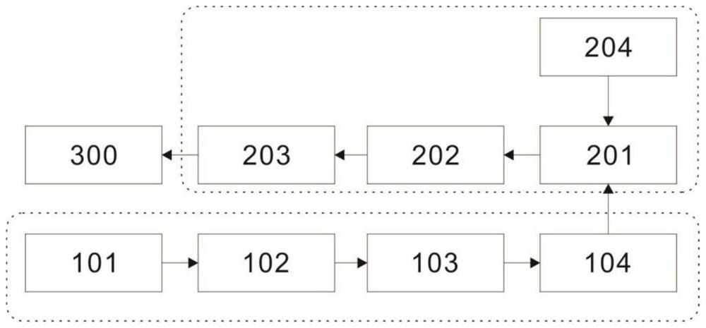
[0040] refer to figure 1 , the present embodiment provides a digital junior high school electrical experiment demonstration device, including a sensing unit 100, an acquisition unit 200, and a processing unit 300, wherein the sensing unit 100 acquires an analog signal of the voltage or current of the circuit under test, and converts the voltage / current The sensor, that is, the sensing unit 100, is connected to the circuit under test. The collected analog signal is first amplified by the operational amplifier circuit of the instrument, then selected by the analog switch, and then entered by the single-chip microcomputer for A / D conversion, and finally through the TYPE The -C data line uses serial communication to transmit digital signals to the acquisition board circuit, and communicates with the acquisition unit 200 in real time, and responds to commands distributed by the acquisition unit 200 in real time.
[0041] Further, the acquisition unit 200 assigns priority to the acqui...
Embodiment 2
[0044] refer to Figure 1-16 , is the second embodiment of the present invention, this embodiment is based on the previous embodiment, and the difference from the previous embodiment is that the sensing unit 100 includes a sequentially connected data signal acquisition and amplification circuit 101, a switch circuit 102, a signal processing The circuit 103 , the first interface circuit 104 , and the signal collected by the sensing unit 100 are transmitted to the collection unit 200 through the collection amplifier circuit 101 , the switch circuit 102 , the signal processing circuit 103 , and the first interface circuit 104 in sequence. Specifically, the acquisition and amplification circuit 101 amplifies the collected signal value, then selects the range through the switch circuit 102, then performs A / D conversion through the signal processing circuit 103, and finally converts the digital value through the TYPE-C data line using serial port communication. The signal is passed ...
PUM
 Abstract
Description
Claims
Application Information
 - R&D Engineer
- R&D Manager
- IP Professional
- Industry Leading Data Capabilities
- Powerful AI technology
- Patent DNA Extraction
Browse by: Latest US Patents, China's latest patents, Technical Efficacy Thesaurus, Application Domain, Technology Topic, Popular Technical Reports.
© 2024 PatSnap. All rights reserved.Legal|Privacy policy|Modern Slavery Act Transparency Statement|Sitemap|About US| Contact US: help@patsnap.com