Uninterruptible power supply, on-off control module, control method and system

A technology of on-off control and control method, which is applied in the direction of emergency power supply arrangements, electrical components, circuit devices, etc., can solve the problems of shortening the service life of devices, increasing costs, and high costs, so as to reduce loss, prolong service life, and low cost Effect

Pending Publication Date: 2022-02-18
HUAWEI DIGITAL POWER TECH CO LTD
View PDF0 Cites 1 Cited by
  • Summary
  • Abstract
  • Description
  • Claims
  • Application Information

AI Technical Summary

Problems solved by technology

[0003] The input side of the UPS is connected to the power supply (mains) through the on-off control module, and the output side of the UPS is connected to the load through the on-off control module. When the on-off control modules on both sides are disconnected, due to the current in the line, The switch itself will have arcing problems, so you can only choose a circuit breaker (Circuit Breaker, CB) or load switch (LoadSwitch, LS) with arc extinguishing function, but the cost of using the above devices is high, the volume is large, and the arcing is still It will shorten the service life of the above devices, so regular maintenance and replacement are required, which further increases the cost

Method used


Image

  • Uninterruptible power supply, on-off control module, control method and system
  • Uninterruptible power supply, on-off control module, control method and system
  • Uninterruptible power supply, on-off control module, control method and system

Examples


Embodiment 1

[0051] An embodiment of the present application provides an uninterruptible power supply, which will be described in detail below with reference to the accompanying drawings.

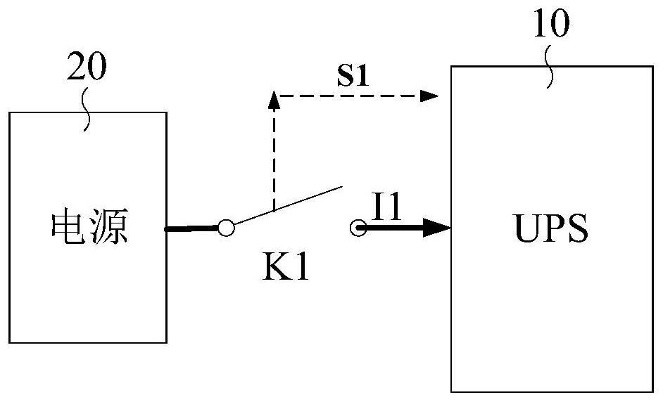
[0052] see figure 2 , which is a schematic diagram of an uninterruptible power supply provided in the embodiment of the present application.

[0053] The input end of the uninterruptible power supply UPS10 shown in the figure is connected to the power supply 20 through the first on-off control module K1.

[0054] In some embodiments, the power source 20 may be mains power.

[0055] The first on-off control module K1 is used for sending the first control signal S1 to the UPS10. The first control signal S1 is used to instruct the controller (not shown in the figure) of the UPS10 to control the current in the line connecting the UPS10 and the first on-off control module K1 to be zero.

[0056] After receiving the first control signal S1, the controller of the UPS10 controls the current in the line conn...

Embodiment 2

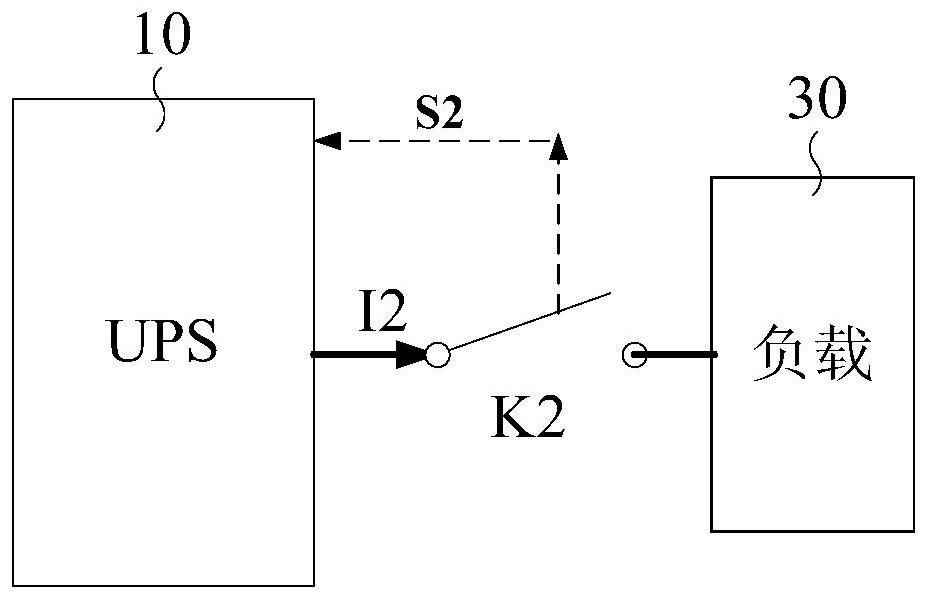
[0060] see image 3 , which is a schematic diagram of another uninterruptible power supply provided by the embodiment of the present application.

[0061] The output terminal of the uninterruptible power supply UPS10 shown in the figure is connected to the load 30 through the second on-off control module K2.

[0062] The second on-off control module K2 is used to send a second control signal S2 to the UPS 10 , and the second control signal S2 is used to instruct a controller (not shown in the figure) of the UPS 10 to control the shutdown of the UPS 10 .

[0063] After receiving the second control signal S2, the controller of the UPS10 controls the UPS10 to shut down, that is, the current I2 at this time is zero.

[0064] When the second on-off control module K2 needs to be turned off, it means that the UPS10 does not need to supply power to the load 30 at this time, so the embodiment of the present application controls the UPS10 to be turned off in advance of the second on-of...

Embodiment 3

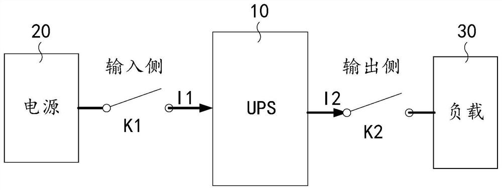
[0068] see Figure 4 , which is a schematic diagram of another uninterruptible power supply provided by the embodiment of the present application.

[0069] The input end of the uninterruptible power supply UPS10 shown in the figure is connected to the power supply 20 through the first on-off control module K1, and the output end is connected to the load 30 through the second on-off control module K2.

[0070] For the working principles of the first on-off control module K1 , the second on-off control module K2 and the controllers of the UPS10 , reference can be made to the above embodiments, and details will not be repeated here in the embodiments of the present application.

[0071] Below to Figure 4 Take an example to illustrate the working principle of the controller when UPS10 is in different working states. for figure 2 or image 3 The working principle of the UPS controller can refer to Figure 4 Corresponding section in the description.

[0072] see Figure 5 ,...


PUM


Abstract

The invention provides an uninterruptible power supply, an on-off control module, a control method and a system, and relates to the technical field of electronic power supply. Wherein the input end of the uninterruptible power supply is connected with a power supply through a first on-off control module, and a controller of the uninterruptible power supply is used for controlling the current in a line, connected with a first on-off control module, of the uninterruptible power supply to be zero after receiving a first control signal sent by the first on-off control module. The output end of the uninterruptible power supply is connected with the load through the second on-off control module, and the controller of the uninterruptible power supply is used for controlling the uninterruptible power supply to be shut down after receiving a second control signal sent by a second on-off control module. According to the technical scheme of the invention, the arc discharge problem can be avoided, so that the cost of using the on-off control module can be reduced.

Description

technical field [0001] The present application relates to the technical field of electronic power, in particular to an uninterruptible power supply, an on-off control module, a control method and a system. Background technique [0002] An uninterruptible power supply (UPS) is a device that can continuously supply power to a load. The UPS mainly includes: a rectifier, an inverter and a battery. When the power input is normal, the power input supplies power to the load through the rectifier and inverter, and the battery is charged through the rectifier, and the UPS can output a stable voltage; supply power to the load. [0003] The input side of the UPS is connected to the power supply (mains) through the on-off control module, and the output side of the UPS is connected to the load through the on-off control module. When the on-off control modules on both sides are disconnected, due to the current in the line, The switch itself will have arcing problems, so you can only cho...

Claims


Application Information

Patent Timeline
IPC IPC(8): H02J9/06
CPCH02J9/06H02J9/062H02M5/4585
Inventor 张春涛
Owner HUAWEI DIGITAL POWER TECH CO LTD
Why Eureka
Try Eureka