Transition speed stabilizing method for mover to pass through junction of magnetic levitation belts
A junction and mover technology, applied in the direction of magnetic attraction or thrust holding device, electric components, magnetic circuit shape/style/structure, etc., can solve the problems of increased load, large belt loss, and reduced belt life
- Summary
- Abstract
- Description
- Claims
- Application Information
AI Technical Summary
Problems solved by technology
Method used
Image
Examples
Embodiment 1
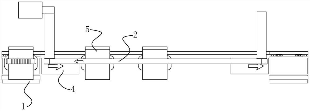
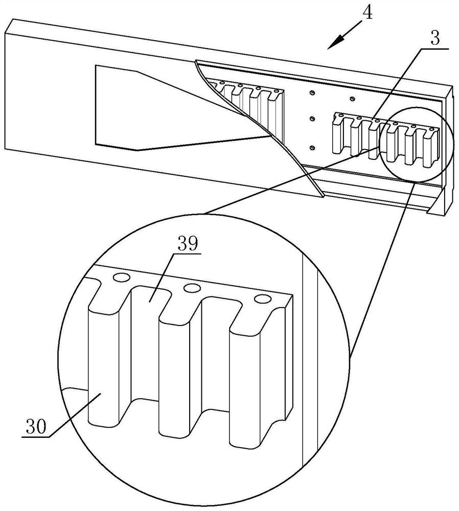
[0039] This embodiment discloses a transitional speed stabilization method for the mover passing through the junction of the maglev line and the belt line. A speed stabilization area is added at the junction 6 of the maglev line 1 and the belt line 2. One end of the speed stabilization area is connected to the maglev line 1 The ends are connected, and the stable speed area covers the area of the belt line 2, and the attraction force gradually decreases from the maglev line 1 to the belt line 2 in the stable speed area. And when the mover 5 passes through the stable speed region, the attractive force decreases uniformly at a constant speed, and the reduction speed of the attractive force is linearly related to the path length of the steady speed region that the mover 5 passes through.
[0040] Based on the above method, this embodiment also discloses a speed stabilization structure corresponding to the above transition speed stabilization method.
[0041] Such as figure 1 T...
Embodiment 2
[0048] This embodiment is similar to Embodiment 1. In this embodiment, the speed stabilizing device 4 includes four silicon steel groups 3, and the thickness ratio of the silicon steel sheets 30 of the magnetic levitation silicon steel group and the silicon steel group 3 in the speed stabilizing device 4 is 1:0.8 in turn. :0.6:0.4:0.2.
[0049] When the mover 5 separates from the magnetic levitation line 1 and passes through the speed stabilizing device 4, the attractive force it receives also decreases step by step according to 1: 0.8: 0.6: 0.4: 0.2.
[0050] On the contrary, when the mover enters the maglev line 1 from the belt line 2 through the speed stabilizing device 4, the attractive force it receives increases according to 0.2:0.4:0.6:0.8:1.
Embodiment 3
[0052] In Embodiment 1 and Embodiment 2, the suction force is adjusted step by step by controlling the thickness of the silicon steel sheet 30 stack.
[0053] And in the present implementation, then be by reducing the mode of silicon steel sheet 30 quantity (referring to Figure 4 , where the shaded part is the silicon steel sheet, and the shaded number is used to refer to the number of silicon steel sheets), to adjust the attraction force, that is, the silicon steel sheet in the maglev silicon steel group, the first silicon steel group 31, the second silicon steel group 32, and the third silicon steel group 33 The quantity ratio of 30 is 1:0.75:0.5:0.25 in turn. And the distance between the silicon steel sheets 30 needs to correspond to the position of the permanent magnet plate at the bottom of the mover 5 . If the spacing between the silicon steel sheets 30 is uneven, the generated attraction will also be unstable.
PUM
 Abstract
Description
Claims
Application Information
 - R&D
- Intellectual Property
- Life Sciences
- Materials
- Tech Scout
- Unparalleled Data Quality
- Higher Quality Content
- 60% Fewer Hallucinations
Browse by: Latest US Patents, China's latest patents, Technical Efficacy Thesaurus, Application Domain, Technology Topic, Popular Technical Reports.
© 2025 PatSnap. All rights reserved.Legal|Privacy policy|Modern Slavery Act Transparency Statement|Sitemap|About US| Contact US: help@patsnap.com


