Direct time-of-flight 3D imaging method and device based on speckle projection

A time-of-flight and imaging device technology, applied in the field of direct time-of-flight 3D imaging methods and devices, can solve problems such as being susceptible to ambient light interference, decreased measurement accuracy, and inaccurate phase measurement, so as to improve energy utilization and reduce light energy loss, the effect of a simple and compact structure

Pending Publication Date: 2022-02-22
深圳市安思疆科技有限公司
View PDF0 Cites 0 Cited by
  • Summary
  • Abstract
  • Description
  • Claims
  • Application Information

AI Technical Summary

Problems solved by technology

This technical solution indirectly obtains the time of flight of light by measuring the phase, and the phase measurement is actually further indirectly realized by relying on the energy intensity of the received light, which will cause the problem of inaccurate phase measurement and is susceptible to ambient light interference , once the distance continues to rise, such as more than 10m, the reflected and received light will be attenuated sharply, or even submerged by ambient light, and the measurement accuracy will drop sharply
At the same time, I-TOF technology essentially uses the average integration method of light energy to obtain the distance value of each pixel on the sensor, so multi-path interference problems will inevitably occur, resulting in unclear outlines of objects, distortion of angular shapes, and inability to distinguish phases. Two adjacent objects etc. problem

Method used


Image

  • Direct time-of-flight 3D imaging method and device based on speckle projection
  • Direct time-of-flight 3D imaging method and device based on speckle projection
  • Direct time-of-flight 3D imaging method and device based on speckle projection

Examples


Embodiment Construction

[0049] In the following description, many specific details are set forth in order to fully understand the present invention, but the present invention can also be implemented in other ways different from those described here, therefore, the present invention is not limited to the specific embodiments disclosed below limit.

[0050] Embodiments of the present invention are described in detail below, examples of which are shown in the drawings, wherein the same or similar reference numerals designate the same or similar elements or elements having the same or similar functions throughout. The embodiments described below by referring to the figures are exemplary and are intended to explain the present invention and should not be construed as limiting the present invention.

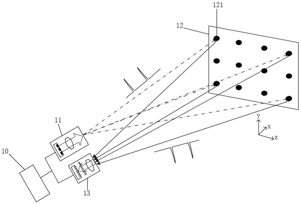
[0051] Such as figure 1 The shown direct time-of-flight 3D imaging device based on speckle projection includes a control processing module 10, a speckle projection module 11 and a SPAD array receiving module...


PUM


Abstract

The invention discloses a direct time-of-flight 3D imaging device based on speckle projection, and the device comprises a speckle projection module which is used for emitting a plurality of light beams and forming speckles which are distributed at intervals on a target surface; an SPAD array receiving module which is used for receiving speckle reflection light beams of a target surface and recording a light receiving moment; and a control processing module which is used for controlling the speckle projection module to emit the light beam, recording the light emitting moment, and processing and generating depth distance information according to the light flight time obtained by the light emitting moment and the light receiving moment. The invention also discloses a direct time-of-flight 3D imaging method based on speckle projection. According to the invention, time recording of two moments of light emission and light reception can be directly realized; and the device has the characteristics of far imaging distance, high signal-to-noise ratio, strong interference resistance, high precision and low power consumption.

Description

technical field [0001] The invention relates to the technical field of photoelectric imaging, in particular to a direct time-of-flight 3D imaging method and device based on speckle projection. Background technique [0002] The 3D imaging device can greatly enrich user experience and enhance product competitiveness. Different from traditional 2D imaging devices, such as cameras, which can only obtain plane 2D information of objects, 3D imaging devices can also obtain depth information of objects and build a three-dimensional 3D model, so 3D imaging devices are widely used in industrial measurement, parts Modeling, medical diagnosis, security monitoring, machine vision, biometrics, augmented reality AR, virtual reality VR and other fields have great application value. [0003] 3D imaging technology is divided into two types: active and passive. The active type uses structured light and time-of-flight technology as the mainstream, and the passive type uses binocular vision as ...

Claims


Application Information

Patent Timeline
Patent Type & Authority Applications(China)
IPC IPC(8): G01S17/894G01S7/481
CPCG01S17/894G01S7/481
Inventor 陈驰李安鲁亚东黄若普
Owner 深圳市安思疆科技有限公司
Why Eureka
Try Eureka