
Solid-sealed polar pole of annular capacitor

A technology of solid-sealed poles and capacitors, which is applied to circuits, electric switches, electrical components, etc., can solve the problems of casting molding yield and reliability decline, increased manufacturing and construction difficulty, and large volume and weight of poles. Insulation withstand ability, good temperature application ability, effect of improving safety margin

Pending Publication Date: 2022-02-22
NR ELECTRIC CO LTD +1
View PDF3 Cites 0 Cited by
  • Summary
  • Abstract
  • Description
  • Claims
  • Application Information

AI Technical Summary

Problems solved by technology

For example, in order to meet the requirements of intelligence, the single-phase on-pole switch fusion equipment should include at least two sets of energy harvesting equipment, one set of current measurement equipment, and two sets of voltage measurement equipment; It goes without saying that the difficulty is self-evident. The patent with the publication number CN210091973U discloses a fusion pole-mounted circuit breaker, which uses a strip-shaped film capacitor, and successfully integrates a current sensor, an integrally cast voltage sensor, and two It is still difficult to meet the needs of all sensors for power-taking capacitors. Although the degree of fusion can be further improved by increasing the capacitance, too many sensors will make the volume and weight of the pole large, greatly increase the difficulty of manufacturing and construction, and lose the meaning of fusion. Potentially reduce casting yield and reliability

Method used


Image

  • Solid-sealed polar pole of annular capacitor
  • Solid-sealed polar pole of annular capacitor
  • Solid-sealed polar pole of annular capacitor

Examples


Embodiment Construction

[0022] The technical solutions and beneficial effects of the present invention will be described in detail below in conjunction with the accompanying drawings.

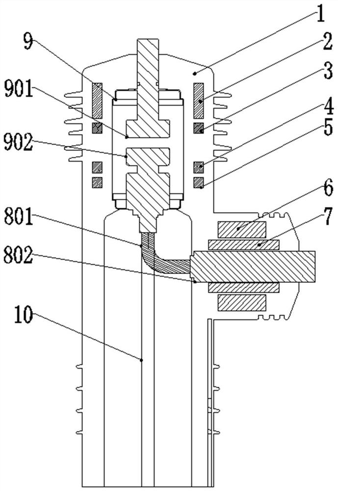
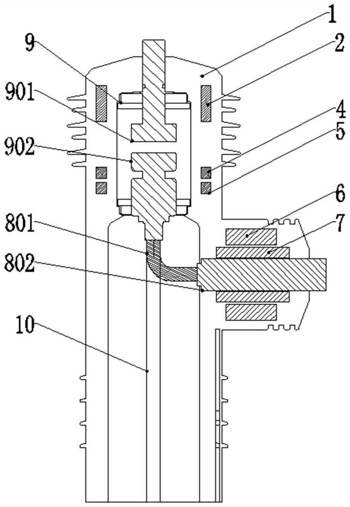
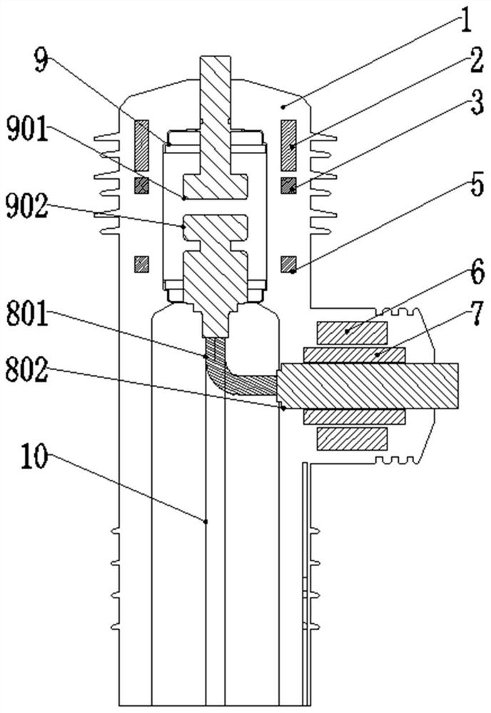
[0023] The invention discloses a solid-sealed pole of an annular capacitor. The upper energy-taking capacitor and the upper phase-sequence measurement capacitor are made of ceramic capacitors, which are designed as rings with the same inner and outer diameters, and coaxially cast on the periphery of the vacuum circuit breaker, and It is placed at the position of the static contact of the vacuum circuit breaker so that the high voltage electrode and the static contact of the vacuum circuit breaker have the same potential.

[0024] The lower phase sequence measurement capacitor and the zero sequence measurement capacitor are designed as rings with the same inner and outer diameters, coaxially cast on the periphery of the vacuum circuit breaker, and placed at the position of the moving contact of the vacuum circuit breake...


PUM


Abstract

The invention discloses a solid-sealed polar pole of an annular capacitor. The solid-sealed polar pole comprises a solid-sealed polar pole epoxy casting body which comprises an epoxy housing, a vacuum circuit breaker and a lower wire outlet conductor which are integrally formed. The moving end of the vacuum circuit breaker is connected with the lower wire outlet conductor through a flexible connection structure. The sensor assembly at least comprises an annular upper energy-taking capacitor which is concentrically arranged on the outer diameter of the vacuum circuit breaker and located in a static contact area, an annular upper phase sequence measuring capacitor which is concentrically arranged outside the vacuum circuit breaker and located in the static contact area and below the upper energy-taking capacitor, and an annular lower phase sequence measuring capacitor which is concentrically arranged on the outer diameter of the vacuum circuit breaker and located in a moving contact area, an annular zero sequence measuring capacitor which is concentrically arranged on the outer diameter of the vacuum circuit breaker and located in the moving contact area and located below the lower phase sequence measuring capacitor, an annular lower energy-taking capacitor which is concentrically arranged outside a lower wire outlet conductor, and an annular current measuring coil which is arranged outside the lower wire outlet conductor and concentrically arranged outside the lower wire outlet conductor and positioned outside the lower energy-taking capacitor.

Description

technical field [0001] The invention belongs to the technical field of electric power equipment, and in particular relates to a solid-sealed pole of a circular capacitor with primary and secondary deep fusion. Background technique [0002] The circuit breaker for smart distribution network is the key equipment of the new generation power grid. Among them, the ZW32 pole-mounted circuit breaker is widely used for its simple structure and maintenance-free features. The development and design of intelligent circuit breakers based on the ZW32 primary and secondary fusion technology have received widespread attention in recent years, and the primary and secondary fusion has gradually evolved from functional integration to equipment integration. The primary breaking device (vacuum circuit breaker), current sensor (LPCT, etc.), voltage sensor (capacitance voltage divider, resistance voltage divider, etc.), energy harvesting equipment, etc. are included in the integrated cast solid-s...

Claims


Application Information

Patent Timeline
Patent Type & Authority Applications(China)
IPC IPC(8): H01H33/66H01H33/662H01H33/02
CPCH01H33/66207H01H33/66H01H33/027
Inventor 于海波熊慕文刘彬卢为王峰曹松华熊杰李啸郭黎黎
Owner NR ELECTRIC CO LTD
Learn More