Novel multi-wire cutting mechanism with variable axial spacing

A multi-wire cutting machine and multi-wire cutting technology, which is applied in the direction of grinding frame, grinding machine parts, working accessories, etc., can solve the problems of poor cutting surface quality, reduced cutting efficiency, and large warpage of cut sheets. , to achieve the effect of convenient operation of the mechanism, reduction of cutting efficiency, and high rigidity of the wire mesh

Active Publication Date: 2022-02-25
DALIAN UNIV OF TECH
View PDF9 Cites 0 Cited by
  • Summary
  • Abstract
  • Description
  • Claims
  • Application Information

AI Technical Summary

Problems solved by technology

When cutting hard materials, if the center distance of the wire roller is too large, the steel wire will produce a larger wire bow during the cutting process, which will reduce the cutting efficiency, the cutting surface quality will be poor, and it is easy to break the wire during the cutting process; the center of the wire roller If the pitch is too small, the size of the cutting workpiece will be limited, large warpage will occur when cutting thin slices, the risk of wire breakage will also increase, and the utilization rate of the machine tool will be limited

Method used


Image

  • Novel multi-wire cutting mechanism with variable axial spacing
  • Novel multi-wire cutting mechanism with variable axial spacing
  • Novel multi-wire cutting mechanism with variable axial spacing

Examples


Embodiment 1

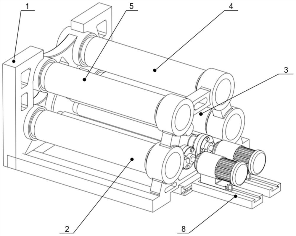
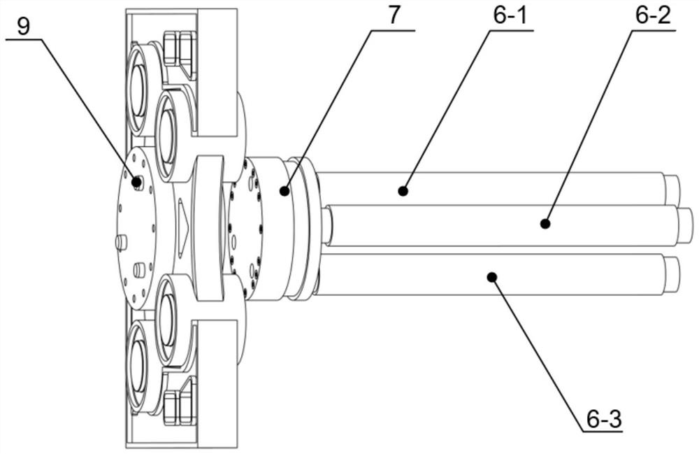
[0052] The invention provides a new multi-wire cutting mechanism with variable axis spacing, which can be applied to a multi-wire roller multi-wire cutting machine. The mechanism includes: frame 1, line roll one 2, line roll two 3, line roll three 4, line roll four 5, line roll five 6-1, line roll six 6-2, line roll seven 6-3, rotor 7. Guide rail 8 and positioning pin 9.

[0053]In this mechanism, wire roller 1, wire roller 3, wire roller 3, wire roller 4, and wire roller 5 have the same specifications and sizes, and are respectively installed on the four front and rear coaxial inner holes of the frame, wire roller 5 6-1, wire roller 6 6-2, Line Roller 7 6-3 The specifications and sizes are exactly the same. According to the three vertices of the triangle inscribed circle as the center of the circle, the rotor 7 is fixed and installed. The rotor is positioned and installed on the inner hole of the frame 1 by three positioning pins 9. According to The geometric characteristics...

Embodiment 2

[0058] A new multi-wire cutting mechanism with variable axis spacing adjusts the center spacing of wire nets in two cutting areas to realize simultaneous cutting of two different workpieces. The mechanism is located in the cutting room of the multi-wire cutting machine, such as figure 1 , figure 2 , including frame 1, line roll one 2, line roll two 3, line roll three 4, line roll four 5, line roll five 6-1, line roll six 6-2, line roll seven 6-3, rotor 7, Guide rail 8, positioning pin 9.

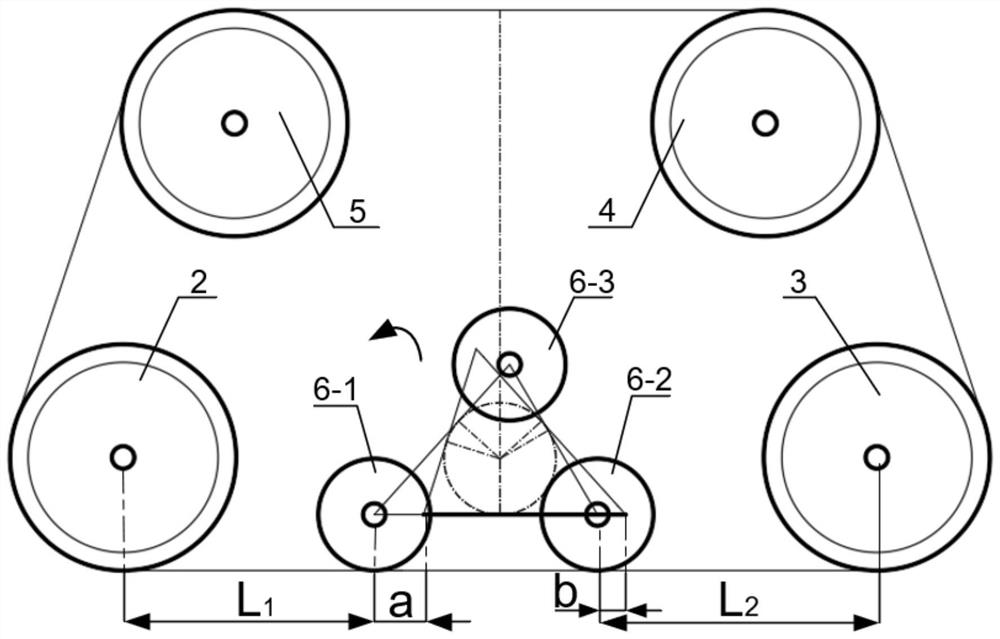
[0059] Wire roll one 2, wire roll two 3, wire roll three 4, and wire roll four 5 are fixedly installed in the four inner holes of the frame, and these four wire rolls are independently driven by four servo motors. Line roll five 6-1, line roll six 6-2, line roll seven 6-3 are fixedly installed with rotor 7, and rotor 7 is installed in the frame inner hole. Cutting wire mesh consists of wire roll one 2, wire roll two 3, wire roll three 4, wire roll four 5 and selected wire roll five 6-1, ...

Embodiment 3

[0063] Such as Figure 5 As shown, different from Embodiment 2, in this embodiment, the circumscribed triangle of the large and small circles on the rotor 7 adopts an isosceles triangle, and the distance between the centers of the wire roller 5 6-1 and the wire roller 6 6-2 is the base e, Line roller five 6-1 and line roller seven 6-3 and line roller six 6-2 and line roller seven 6-3 center distances are all waist f.

[0064] When selecting line roll five 6-1 and line roll six 6-2 as the working line rolls in the present embodiment, the wire mesh is composed of line roll one 2, line roll two 3, line roll three 4, line roll four 5 and line roll five 6-1, wire roller six 6-2 winding work, the wire under the wire net is evenly divided into two cutting areas with the same spacing by wire roller five 6-1 and wire roller six 6-2, wire roller one 2 and wire roller Five 6-1 center horizontal spacing is L 3 , the horizontal distance between the centers of line roll two 3 and line rol...


PUM

PropertyMeasurementUnit
diameteraaaaaaaaaa

Abstract

The invention provides a novel multi-wire cutting mechanism with variable axial spacing, which comprises a rack, a first wire roller, a second wire roller, a third wire roller, a fourth wire roller and a rotor, wherein the first wire roller, the second wire roller, the third wire roller and the fourth wire roller are respectively driven by four servo motors, the rotor is provided with a fifth wire roller, a sixth wire roller and a seventh wire roller, and the connecting lines of the centers of the fifth wire roller, the sixth wire roller and the seventh wire roller form a triangle; a containing space is formed in the first wire roller, the second wire roller, the third wire roller and the fourth wire roller, and the fifth wire roller, the sixth wire roller and the seventh wire roller are all located in the containing space. The cutting wire net is supported and wound by any two of the first wire roller, the second wire roller, the third wire roller, the fourth wire roller, the fifth wire roller, the sixth wire roller and the seventh wire roller. And the rotor is rotated, so that two different wire rollers in the fifth wire roller, the sixth wire roller and the seventh wire roller serve as working wire rollers to support the lower flat cable net to participate in material cutting, the center distance between the wire nets of the left cutting area and the right cutting area is adjusted, and two different workpieces can be cut at the same time.

Description

technical field [0001] The invention relates to the technical field of cutting equipment, in particular to a new mechanism for multi-wire cutting with variable interaxial spacing. Background technique [0002] The multi-wire cutting machine is a processing equipment that uses a consolidated abrasive steel wire or a high-speed reciprocating steel wire to bring the abrasive into the processing area for grinding. The common cutting materials are mostly brittle and hard materials, such as semiconductor materials (silicon ingots, silicon carbide ), glass and magnetic materials such as NdFeB, etc., the workpiece can be uniformly cut into tens or hundreds of pieces, and the bending degree (BOW) of the multi-wire machine cutting material is small, the warp (Warp) is small, and the parallelism (Tarp) Good, total thickness tolerance (TTV) is small, and cutting loss between sheets is small. [0003] In order to make thinner slices and reduce material loss when cutting materials, multi...

Claims


Application Information

Patent Timeline
Patent Type & Authority Applications(China)
IPC IPC(8): B28D5/04B28D1/22B28D7/00B24B27/06B24B41/02B24B47/00
CPCB28D5/045B28D5/0058B28D1/22B28D7/00B24B27/0633B24B27/0683B24B41/02B24B47/00
Inventor 张振宇万省作吴斌孟凡宁张富旭顾秦铭冯俊元
Owner DALIAN UNIV OF TECH
Why Eureka
Try Eureka