Emergency transfer device for salt production conveying line
A transfer device and conveying line technology, applied in the direction of conveyor control devices, conveyors, conveyor objects, etc., can solve the problems of screw conveying channel blockage, difficult to clean, etc., and achieve the effect of efficient identification
- Summary
- Abstract
- Description
- Claims
- Application Information
AI Technical Summary
Problems solved by technology
Method used
Image

Examples
Embodiment 1
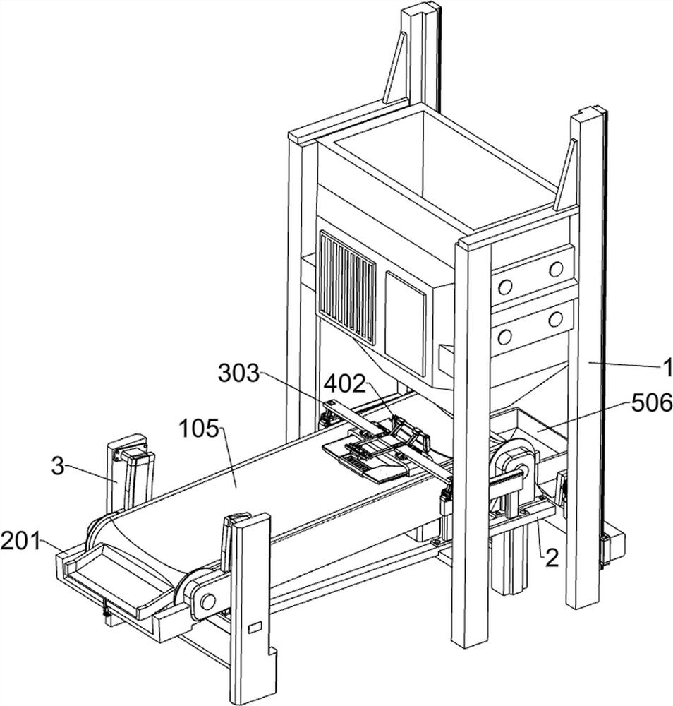
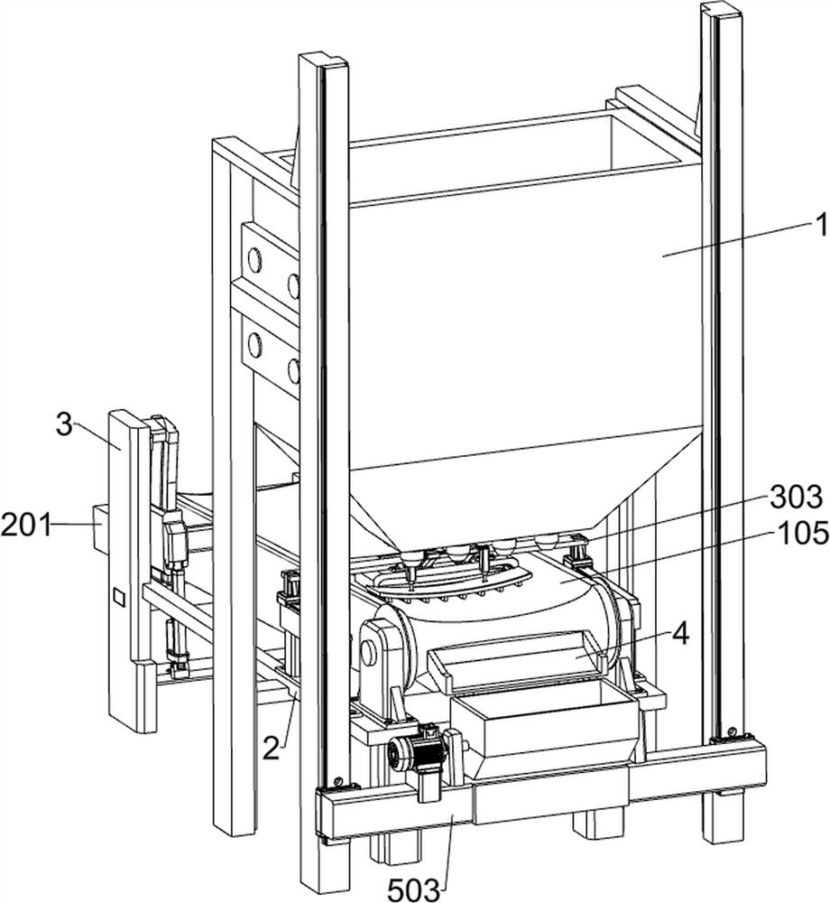
[0032] An emergency transfer device for a salt production conveyor line, such as Figure 1-2 As shown, it includes a conveying unit, a left collecting unit, a visual recognition unit, an auxiliary unit, a dryer 1, a right support 2, a left support 3 and a right feeding plate 4; the lower side of the dryer 1 is solid The right support 2 is connected; the left support 3 is fixedly connected to the left side of the right support 2; the right feeding plate 4 is fixedly connected to the right side of the right support 2; between the right support 2 and the left support 3 , is connected with a delivery unit; the left side of the delivery unit is connected with a left collection unit; the upper side of the right bracket 2 is connected with a visual recognition unit; the right side of the visual recognition unit is connected with an auxiliary unit.
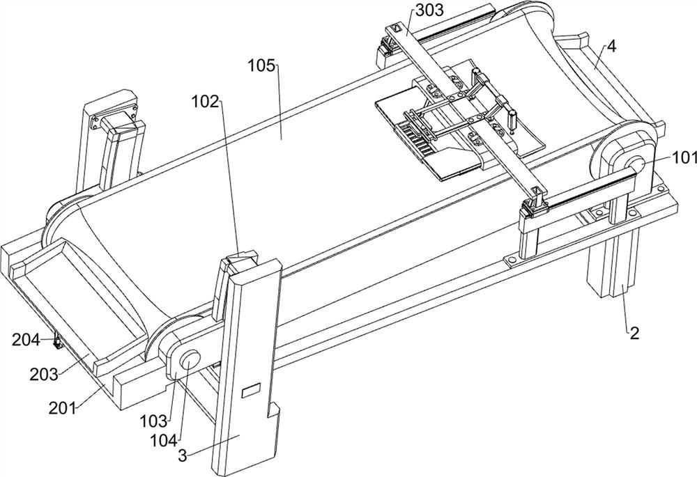
[0033] Such as Figure 3-4As shown, the conveying unit includes a right motorized roller 101, an arc-shaped slide rail 102, a sliding b...
Embodiment 2
[0043] Such as Figure 1-2 , Figure 11 As shown, on the basis of Embodiment 1, a transfer unit is also included. The right side of the dryer 1 is provided with a transfer unit. The transfer unit includes a second slide rail 501, a second electric slider 502, and a third fixed plate. 503, steering motor 504, second rotating shaft 505 and transfer bucket 506; the front part on the right side of the dryer 1 and the rear part on the right side are each fixedly connected with a second slide rail 501; two second slide rails 501 A second electric slider 502 is slidingly connected to each of the lower sides of the two second electric sliders 502; a third fixing plate 503 is bolted between the right sides of the two second electric sliders 502; the front bolt on the upper side of the third fixing plate 503 is connected with The steering motor 504; the middle part of the upper side of the third fixed plate 503 is rotatably connected with the second rotating shaft 505; the middle part ...
PUM
 Abstract
Description
Claims
Application Information
 - Generate Ideas
- Intellectual Property
- Life Sciences
- Materials
- Tech Scout
- Unparalleled Data Quality
- Higher Quality Content
- 60% Fewer Hallucinations
Browse by: Latest US Patents, China's latest patents, Technical Efficacy Thesaurus, Application Domain, Technology Topic, Popular Technical Reports.
© 2025 PatSnap. All rights reserved.Legal|Privacy policy|Modern Slavery Act Transparency Statement|Sitemap|About US| Contact US: help@patsnap.com