Eureka AIR delivers breakthrough ideas for toughest innovation challenges, trusted by R&D personnel around the world.

LNG conveying and filling system and control method thereof

The technology of a filling system and a control method is applied in the field of LNG gas transportation and filling system and its control, and can solve the problems of increased gasification volume, small gasification volume, and small liquid filling volume of storage tanks.

Pending Publication Date: 2022-02-25
ENRIC (LANGFANG) ENERGY EQUIP INTEGRATION CO LTD +2
View PDF14 Cites 0 Cited by
  • Summary
  • Abstract
  • Description
  • Claims
  • Application Information

AI Technical Summary

Problems solved by technology

[0003] In the related technology, when the LNG refueling station has a small demand for locomotive refueling in the off-season, the amount of liquid added is small, and the storage time of the LNG in the storage tank is longer. When there is no locomotive refueling for a long time, the filling pipeline Liquefied natural gas vaporizes due to absorbing a large amount of external heat, so it is easy to cause the gasification volume in the storage tank to increase. When the pressure reaches the set threshold, the filling system needs to release the pressure externally, so there will be a problem of continuous loss of LNG
In addition, during the peak season when the demand for refueling of locomotives is high, the LNG refueling station will add a large amount of liquid. The storage time of LNG in the storage tank is relatively short, and it will be continuously transported to the locomotive. The gasification amount is very small, so it is easy to As a result, the air pressure in the storage tank is low, so there are often problems of low storage tank pressure and slow liquid supply speed in the LNG delivery and filling system

Method used

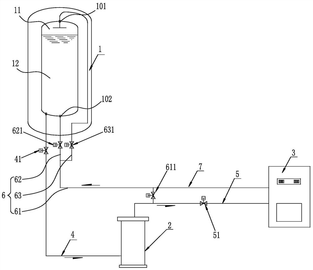
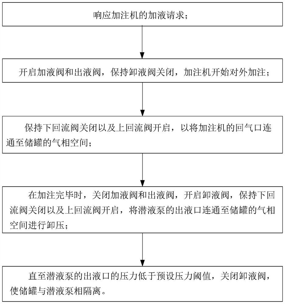
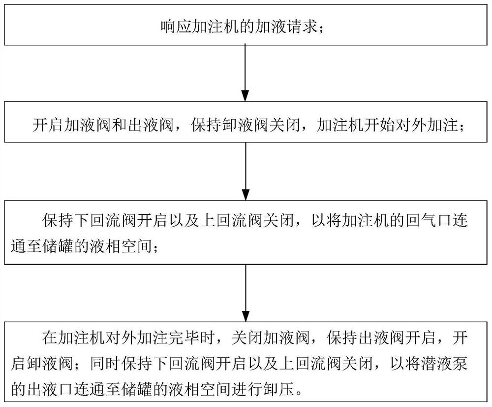

Image

  • LNG conveying and filling system and control method thereof
  • LNG conveying and filling system and control method thereof
  • LNG conveying and filling system and control method thereof

Examples


Embodiment Construction

[0032] Typical embodiments that embody the features and advantages of the present invention will be described in detail in the following description. It should be understood that the present invention is capable of various changes in different embodiments without departing from the scope of the present invention, and that the description and illustrations therein are illustrative in nature and not limiting. this invention.

[0033] In the description of the present application, it should be understood that the terms "center", "longitudinal", "transverse", "length", "width", "thickness", "upper", "lower", "front", " Orientation indicated by rear, left, right, vertical, horizontal, top, bottom, inside, outside, clockwise, counterclockwise, etc. The positional relationship is based on the orientation or positional relationship shown in the drawings, which is only for the convenience of describing the application and simplifying the description, and does not indicate or imply tha...


PUM


Abstract

The invention relates to an LNG conveying and filling system and a control method thereof. A liquid outlet pipeline in the filling system is communicated with a storage tank and an immersed pump; a liquid outlet valve is arranged on the liquid outlet pipeline; a liquid adding pipeline is communicated with the immersed pump and a filling machine, and a liquid adding valve is arranged on the liquid adding pipeline; a return pipeline is provided with an inlet branch and two outlet branches; the inlet branch is connected with the immersed pump, and a liquid discharge valve is arranged on the inlet branch; the two outlet branches are connected with a lower return port and an upper return port respectively, and a lower return valve and an upper return valve are arranged on the two outlet branches respectively; the gas return pipeline is communicated with the filling machine and the inlet branch; when the liquid adding valve is in a closed state, the liquid outlet valve and the liquid discharge valve are both closed or opened; and one of a lower return valve and an upper return valve is opened. The storage tank and the filling machine are controlled to be isolated or communicated through the liquid outlet valve and the liquid discharge valve, and the upper return valve and the lower return valve are matched to control the lower return port and the upper return port to be opened alternatively; and the filling system can select and use different control modes according to different periods of locomotive gas filling demand quantity.

Description

technical field [0001] The invention relates to the technical field of LNG refueling, in particular to an LNG gas delivery and refueling system and a control method thereof. Background technique [0002] Liquefied natural gas (LNG) locomotives require a dedicated LNG gas delivery and filling system. The LNG filling station is composed of storage tanks, submersible pump skids and LNG filling machines. [0003] In the related technology, when the LNG refueling station has a small demand for locomotive refueling in the off-season, the amount of liquid added is small, and the storage time of the LNG in the storage tank is longer. When there is no locomotive refueling for a long time, the filling pipeline LNG vaporizes due to absorbing a large amount of external heat, so it is easy to cause the gasification volume in the storage tank to increase. When the pressure reaches the set threshold, the filling system needs to release the pressure externally, so there will be a problem o...

Claims


Application Information

Patent Timeline
Patent Type & Authority Applications(China)
IPC IPC(8): F17D1/14F17D1/00F17D3/01F17D5/00F17C7/02F17C5/02F17C5/06F17C13/00F17C13/04
CPCF17D1/14F17D1/005F17D3/01F17D5/00F17C7/02F17C5/02F17C5/06F17C13/00F17C13/04F17C2205/0352F17C2221/033F17C2223/0153F17C2225/013F17C2227/0135F17C2227/0192F17C2227/0302F17C2227/0369F17C2227/039F17C2250/0626F17C2260/025F17C2265/065
Inventor 钟伟明朱文亮张鹏娜孙林史建伟张文凯
Owner ENRIC (LANGFANG) ENERGY EQUIP INTEGRATION CO LTD
Why Eureka
Eureka Blog
Learn More