Calcium adding method for deoxidation calcium treatment of liquid steel

A technology of calcium treatment and molten steel, applied in the field of calcium addition in molten steel deoxidation calcium treatment, can solve the problems of serious steel slag splashing, not feeding line speed, nitrogen increase of molten steel, etc., to improve utilization rate and recovery rate, and slow down heat transfer, solve the effect of nitrogen increase in molten steel

Active Publication Date: 2013-12-18
ZHANJIANG SHENGBAO TECH CO LTD
View PDF7 Cites 2 Cited by
  • Summary
  • Abstract
  • Description
  • Claims
  • Application Information

AI Technical Summary

Problems solved by technology

[0007] Several existing types of cored wires containing calcium or calcium alloys still have the following defects: (1) Silicon-containing low-calcium alloy cored wires, such as CaSi cored wires: the disadvantage is that calcium is removed during the refining process outside the furnace. It not only causes silicon increase in molten steel during treatment, but also has high treatment costs, so it is not suitable for low-Si steel types for calcium treatment
(2) Core-spun wire containing a mixture of silicon-calcium grains, iron grains, and calcium grains, such as Fe+Ca powder cored wire: the disadvantage is that powdery metal calcium has a large specific surface area and is easily oxidized
In addition, at the refining temperature, when the outer cladding is melted, the exposed metallic calcium gasifies rapidly, which easily causes violent tumbling and splashing of the steel slag liquid surface, and not only the calcium recovery rate is low (the calcium recovery rate is only 8%-12% ), it will also cause nitrogen increase in molten steel and produce unsafe factors
(3) Core-spun wire containing pure calcium wire, for example, the diameter of calcium wire is 7.5 mm, and the thickness of iron sheet is 0.55 mm. Not only is the steel slag splashing serious, but it will also cause the molten steel to increase nitrogen by 5-8PPM and seriously endanger the production safety of the steel plant.
The resulting feeding speed is obviously roughly estimated, not the best feeding speed, and the utilization rate of calcium metal has not reached the best.

Method used


Image

  • Calcium adding method for deoxidation calcium treatment of liquid steel
  • Calcium adding method for deoxidation calcium treatment of liquid steel
  • Calcium adding method for deoxidation calcium treatment of liquid steel

Examples


Embodiment 1

[0039] Embodiment 1: In this embodiment, the specification parameters of the calcium core wire with composite structure and the comprehensive parameters when feeding the wire are as follows:

[0040](1) The diameter D of the composite structure calcium core wire in this embodiment is 9mm;

[0041] (2) Outer cladding: steel strip thickness 0.5mm;

[0042] (3) Middle layer: steel strip thickness 0.8mm;

[0043] (4) Calcium core diameter: 6.4mm;

[0044] (5) Ladle inner diameter: 3010mm, molten steel depth: 3700mm;

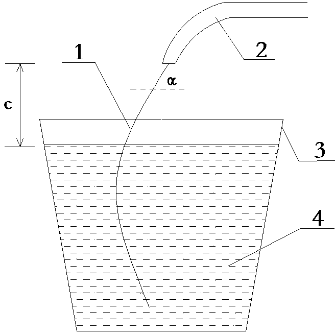
[0045] (6) The incident angle α of the calcium core wire is 53°, and the feeding speed is 3m / s.

[0046] Such as figure 1 , 2 As shown, when the calcium core wire 1 is fed into the molten steel 4 in the ladle 3, except the incident height c of the calcium core wire 1 is different, all other parameters are the same; the use effect is shown in the following table:

[0047] Ca core incident height c (CM) 25 30 38 40 42 50 55 Calcium yield (%)...

Embodiment 2

[0049] Embodiment 2: In the present embodiment, the specification parameters of the composite structure calcium core wire and the comprehensive parameters during wire feeding are as follows:

[0050] (1) The diameter D of the composite structure calcium core wire in this embodiment is 9mm;

[0051] (2) Outer cladding: steel strip thickness 0.5mm;

[0052] (3) Middle layer: steel strip thickness 0.8mm;

[0053] (4) Calcium core diameter: 6.4mm;

[0054] (5) Ladle inner diameter: 3010mm, molten steel depth: 3700mm;

[0055] (6) The incident height of the calcium core wire is 40cm, and the feeding speed is 3m / s.

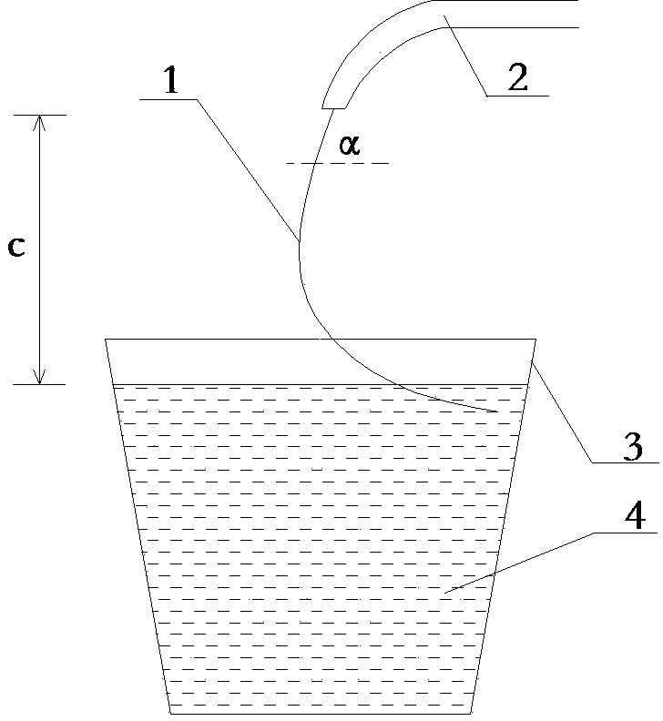
[0056] Such as figure 1 , 2 As shown, when the calcium core wire 1 is fed into the molten steel 4 in the ladle 3, except the incident angle α of the calcium core wire 1 is different, the other parameters are the same; the use effect is shown in the following table:

[0057] Ca core incident angle α 35 40 45 53 55 57 65 70 Calcium yield (%) ...

Embodiment 3

[0059] Embodiment three: the present embodiment will carry out the test of two batches, and the specification parameter of composite structure calcium core wire in the first batch and the comprehensive parameter when feeding wire are as follows:

[0060] (1) The diameter D of this batch of composite structure calcium core wire is 8.9mm;

[0061] (2) Outer cladding: steel strip thickness 0.5mm;

[0062] (3) Middle layer: steel strip thickness 0.8mm;

[0063] (4) Calcium core diameter: 6.3mm;

[0064] (5) Ladle inner diameter: 3400mm, molten steel depth: 4250mm;

[0065] (6) The incident height c of the calcium core wire is 40cm, and the incident angle α is 55°.

[0066] The specification parameters of the composite structure calcium core wire in the second batch and the comprehensive parameters when feeding the wire are as follows:

[0067] (1) The diameter D of this batch of composite structure calcium core wire is 10.1mm;

[0068] (2) Outer cladding: steel strip thicknes...


PUM

PropertyMeasurementUnit
diameteraaaaaaaaaa
thicknessaaaaaaaaaa
diameteraaaaaaaaaa

Abstract

The invention belongs to steelmaking external refining technologies and particularly relates to a calcium adding method for deoxidation calcium treatment of liquid steel. The calcium adding method is characterized in that a calcium core wire with a composite structure is adopted and consists of a calcium core, a middle layer and a coating layer, wherein the coating layer wraps the outside surface of the middle layer, the middle layer wraps the outside surface of the calcium core, and the diameter of the calcium core is 6-8mm; the height of incidence of the calcium core wire is that the calcium core wire is just above the liquid surface of the liquid steel in a ladle by 38-42cm, and the angle of incidence of the calcium core wire is that the calcium core wire and the liquid surface of the liquid steel in the ladle form an included angle of 53-57 degrees. The calcium adding method has the advantages that the problem of splashing during the calcium treatment of the liquid steel can be effectively solved due to the adoption of the calcium core wire with the composite structure; meanwhile, the calcium core wire feeding success rate is increased through adopting the best feeding speed, height of incidence and angle of incidence, so that the yield of calcium metal is increased.

Description

technical field [0001] The invention belongs to the refining technology outside a steelmaking furnace, and in particular relates to a calcium addition method for deoxidizing calcium treatment of molten steel. Background technique [0002] Calcium treatment is a molten steel refining method developed in the 1970s. Historically, there have been methods such as adding calcium alloy directly into the ladle and spraying calcium alloy into molten steel. However, due to unstable treatment effects or excessive cost Higher causes have been gradually eliminated, and now the method of ladle feeding calcium wire is used. It wraps calcium alloy (Ca, Ca-Si, Ca-Fe, etc.) with steel skin to make cored wire, and inserts it into molten steel at a high speed through the guide tube of the wire feeder. During the wire feeding process, it is accompanied by inert gas stirring to increase the residence time of Ca in the molten steel and to carry out good mixing. This approach is widely used in st...

Claims


Application Information

Patent Timeline
Patent Type & Authority Applications(China)
IPC IPC(8): C21C7/06
Inventor 刘欣隆孙树森周四明
Owner ZHANJIANG SHENGBAO TECH CO LTD
Why Eureka
Try Eureka