Satellite-to-ground camera imaging system for direction measurement of optical remote sensing satellite

An optical remote sensing and imaging system technology, applied in the field of remote sensing satellite imaging, can solve the problems of difficult to guarantee pointing accuracy, complex mathematical models, and limited pointing solution accuracy, and achieves the effect of strong ease of use and improved surveying and mapping accuracy

Pending Publication Date: 2022-02-25
CHANGCHUN INST OF OPTICS FINE MECHANICS & PHYSICS CHINESE ACAD OF SCI
View PDF0 Cites 2 Cited by
  • Summary
  • Abstract
  • Description
  • Claims
  • Application Information

AI Technical Summary

Problems solved by technology

The mathematical model of this process is complex, and the model parameters are constantly changing, which limits the calculatio

Method used


Image

  • Satellite-to-ground camera imaging system for direction measurement of optical remote sensing satellite
  • Satellite-to-ground camera imaging system for direction measurement of optical remote sensing satellite
  • Satellite-to-ground camera imaging system for direction measurement of optical remote sensing satellite

Examples


Embodiment 1

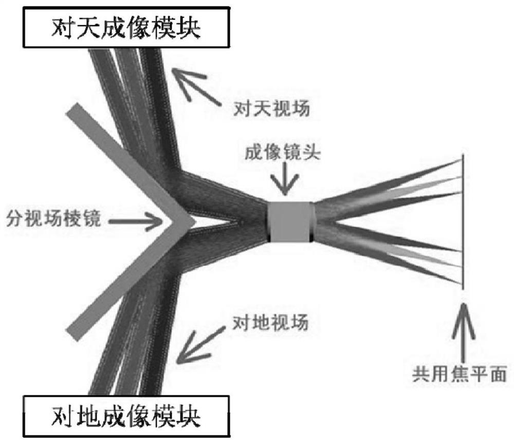
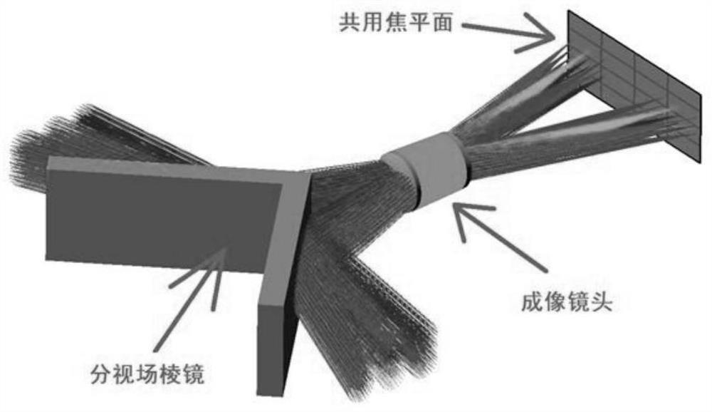
[0021] Such as figure 1 As shown, an imaging system for a star-earth camera includes a field-of-view prism, a shared imaging lens, a shared imaging detector and a processing module, and the field-of-view prism is formed by two angles, such as mutually perpendicular The reflective surface is formed, and the imaging detector is placed at the focal plane of the imaging lens. Functionally, the imaging system can be divided into a sky imaging module and an earth imaging module.

[0022] The sky imaging module is used for star imaging, and the light from the starry sky is reflected by one of the reflection surfaces of the field-of-view prism and enters the imaging lens. It should be noted that, in the field of view of the star-to-earth camera, the working principle of the star-to-sky imaging module is similar to that of the star camera or star sensor. They all use star imaging, pixel subdivision and high-precision attitude calculation, etc. Technology completes its orientation and...

Embodiment 2

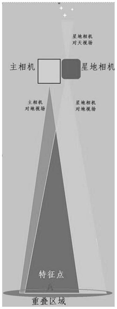
[0027] In order to ensure high-precision imaging and positioning of optical remote sensing satellites, it is necessary to solve the boresight pointing of optical remote sensing satellites with high precision. Based on the above embodiments, the satellite attitude determination and the main load boresight can be directly related through the optical imaging of the satellite-ground camera, so as to realize satellite Accurate measurement of attitude and principal load boresight. Its working principle is: the imaging lens of the star-ground camera passes through the front-end field of view beamsplitter prism to simultaneously image the starry sky and the ground, and the two images are imaged on the same focal plane; the image of the starry sky is used to calculate the satellite attitude data, and then calibrate The relationship between the field of view of the earth and the attitude of the satellite; there is an overlapping area between the field of view of the satellite-ground came...


PUM


Abstract

The invention provides a satellite-to-ground camera imaging system for high-precision direction measurement of an optical remote sensing satellite, a field of view of a satellite-to-ground camera is divided into an over-the-sky field of view and an over-the-ground field of view, and the two fields of view are in a common-optical-path integrated design, so that a visual axis relation between an over-the-sky imaging module and an over-the-ground imaging module is stable; therefore, through common-path imaging on the sky and the ground and matching with other position resolving algorithms, high-precision calibration, positioning and even surveying and mapping tasks on the ground object position can be completed; based on the stable visual axis relation between a satellite-to-ground camera to the over-the-sky imaging module and the over-the-ground imaging module, the optical remote sensing satellite direction correction system firstly determines the visual axis direction of the to-the-ground imaging module in combination with the star map orientation acquired by the over-the-sky imaging module; and image matching is carried out according to image data obtained by ground imaging of the main camera and ground imaging data of the satellite-to-ground camera so as to further correct errors of the visual axis pointing of the main camera, so that the visual axis pointing of the main camera is calculated with high precision, and the surveying and mapping precision of the main camera is improved.

Description

technical field [0001] The invention belongs to the technical field of remote sensing satellite imaging, in particular to a satellite-ground camera imaging system for high-precision pointing measurement of optical remote sensing satellites. Background technique [0002] In the traditional method of using star sensor or star camera for optical remote sensing satellite pointing measurement, the star sensor or star camera boresight is fixedly connected with the main camera (load) structure, and the distance between the main camera and the star sensor boresight is determined in the ground laboratory. When working in orbit, it is assumed that the relative relationship is fixed, and on this basis, the camera pointing, etc. are measured and calibrated. In fact, due to the influence of material, humidity, weight changes, and satellite launch process and on-orbit operating environment changes, the relative relationship will inevitably change, becoming the largest and difficult to mea...

Claims


Application Information

Patent Timeline
IPC IPC(8): G01C11/00
CPCG01C11/00
Inventor 陈长征陈哲张星祥聂婷
Owner CHANGCHUN INST OF OPTICS FINE MECHANICS & PHYSICS CHINESE ACAD OF SCI
Why Eureka
Try Eureka