Method and device for improving energy efficiency of integrated energy system and terminal equipment

A comprehensive energy system and energy efficiency technology, applied in the field of energy planning, can solve the problems of energy waste and low energy efficiency improvement

Pending Publication Date: 2022-02-25
ZAOZHUANG POWER SUPPLY COMPANY OF STATE GRID SHANDONG ELECTRIC POWER +1
0 Cites 0 Cited by

AI-Extracted Technical Summary

Problems solved by technology

[0004] However, in the actual application process, although the integrated energy system realizes the coordinated couplin...

Method used

The basic features of the integrated energy system itself are: 1. the use of the integrated energy system can effectively reduce carbon emissions and other pollutant emissions, and it is green and environmentally friendly; 2. the integrated energy system can coordinate the advantages of different energy supply systems, and realize the different energy sources ...

Abstract

The invention is suitable for the technical field of energy planning, and provides a method and device for improving the energy efficiency of an integrated energy system, and terminal equipment, and the method comprises the steps: obtaining the energy data of the integrated energy system; establishing an energy flow diagram model of the integrated energy system according to the energy data of the integrated energy system; based on the energy flow diagram model of the integrated energy system and the constraint conditions, determining the constraint conditions of the energy flow diagram model of the integrated energy system; based on the integrated energy system energy flow diagram model and the efficiency, determining an integrated energy system energy flow diagram model evaluation index; and determining an energy efficiency improvement model of the integrated energy system by utilizing a genetic algorithm based on the constraint condition of the energy flow diagram model of the integrated energy system and the evaluation index of the energy flow diagram model of the integrated energy system. The invention provides a method for constructing an integrated energy system model with improved energy efficiency by comprehensively analyzing the characteristics of the integrated energy system by taking energy efficiency improvement maximization as a target, and provides instructive suggestions for design and planning of the integrated energy system.

Application Domain

ResourcesGenetic algorithms

Technology Topic

Genetics algorithmsProcess engineering +8

Image

  • Method and device for improving energy efficiency of integrated energy system and terminal equipment
  • Method and device for improving energy efficiency of integrated energy system and terminal equipment
  • Method and device for improving energy efficiency of integrated energy system and terminal equipment

Examples

  • Experimental program(1)

Example Embodiment

[0077] In the following description, specific details such as specific system structures and techniques are proposed for explanation, such as specific details, such as specific system structures, and techniques. However, it will be apparent to those skilled in the art that the present application can also be implemented in other embodiments without these specific details. In other cases, a detailed description of well known systems, devices, circuits, and methods is omitted to prevent unnecessary details to prevent the presentation.
[0078] It should be understood that when used in the present application and the appended claims, the term "comprising" indicates the existence described in the description, the overall, steps, operations, elements, and / or components, but does not exclude one or more other Features, overall, steps, operations, elements, components, and / or their set presence or addition.
[0079] It should also be understood that terms "and / or" as used in the present application and the appended claims are any combination of one or more of the related items, and all possible combinations, and including these combinations.
[0080] As used in the present application specification and the appended claims, the term "if" can be interpreted as "when" or "once" in response to determination "or" in response to determination "or" once "according to the context ". Similarly, the phrase "if it is determined" or "if the [described" or event] "can be explained in accordance with the context to mean" once it is determined "or" in response to determination "or" detected [described condition or event " ] "Or" in response to detecting [described conditions or events] ".
[0081] In addition, in the description of the present application and the appended claims, the terms "first", "second", "third", etc. are only used to distinguish the description, and cannot be understood as an indication or implied relative importance.
[0082] Reference "One Embodiment" or "Some Embodiment" described in the present application specification means that in one or more embodiments of the present application, including the specific features, structures, or characteristics described in connection with this embodiment. Thus, the statement "in one embodiment" in one embodiment is "in one embodiment", "in some embodiments", "in other embodiments", "in some other embodiments" is not necessarily inevitable. Referring to the same embodiment, it means "one or more but not all embodiments" unless otherwise particularly emphasized. The terms "including", "comprising", "having" and their deformation means "including, but not limited to," unless otherwise particularly emphasized in other ways.
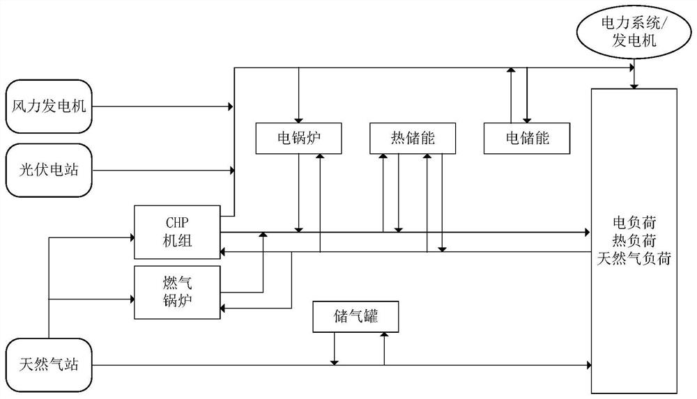
[0083] figure 1 It is a schematic diagram of architectural diagrams of the integrated energy system provided by an embodiment of this application. figure 1 As shown, three systems of electricity, heat, natural gas and energy conversion equipment as coupling are forms a comprehensive energy system. The power system is responsible for the production, delivery, distribution and consumption of electrical energy; the heat system is responsible for the heat source to be transported to the heat load. After the heat-load heat sink, the high temperature hot water turns low temperature hot water, and then After returning the heat network, the natural gas system is responsible for the production of natural gas (generated by the gas source), transporting (completed by the air supply pipeline) and consumption (completed by natural gas load), in order to ensure pressure, the natural gas system also requires compressor; Equipment such as CHP (thermoelectric joint production), CCHP (hot and electric cogeneration), electric boiler and gas boiler is used to complete conversion between different energy sources.
[0084] The basic features of the integrated energy system itself are: 1 The use of integrated energy systems can effectively reduce carbon emissions and other pollutants emissions, green environmental protection; 2 Integrated energy systems can coordinate the advantages of different supply power systems, and achieve optimization of different energy systems Scheduling; 3 Integrated energy systems can integrate optimal utilization in different energy forms.
[0085] analyze figure 1 The schematic diagram shown in the integrated energy system, which includes the main features of the power system, thermal system, and natural gas system:
[0086] 1) Physical parameters involving a variety of energy sectors, such as electricity, heat / cold, gas, etc., and follow physical laws are not uniform. The power system complies with electromagnetic law and circuit law; the thermal system (heating / cooling system) contains hydraulic model and thermal model, follows fluid mechanics and thermodynamic law; and the natural gas system follows fluid mechanics law.
[0087] 2) Multi-energy-flow coupling, physically high heterogeneous. The difference in physical properties of the power system, the heat system, and the natural gas system is large, which belongs to a plurality of heterogeneous energy flow systems, coupled together via CHP, CCHP, electrical heating, heat pump, electric hydrogen, etc.
[0088] 3) Each subsystem time scale is different and has different dynamic processes. The time constant of the power system, the fastest change speed; the thermal system is the largest, the speed is slower; the time constant of the natural gas system and the speed of change, which in turn leads to a multi-time scale characteristic of the integrated energy system.
[0089] In summary, although the integrated energy system enables energy-wide coupling, efficient delivery, reasonable allocation, a high utilization rate of energy systems. However, due to the variety of reasons, the energy efficiency of the integrated energy system has caused great waste on the utilization of energy.
[0090] Based on the above problems, the present application provides methods, devices, and terminal devices that can effectively improve the energy efficiency of integrated energy systems.
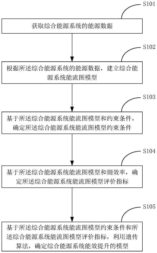
[0091] figure 2 It is a flow chart showing the method of the energy efficiency improvement of the integrated energy system provided by an embodiment of the present application. figure 2 Detailed detailing this method is as follows:
[0092] In step S101, the energy data of the integrated energy system is acquired.
[0093] In some embodiments, the acquired integrated energy system energy data is data contained in the system, such as power source data, thermal energy data, and natural gas energy data.
[0094] Optionally, integrated energy system energy data also includes all supply, exchange, storage, consumer energy equipment installed, and operational power.
[0095] In step S102, the energy flow map model of the integrated energy system can be established according to the energy data of the integrated energy system.
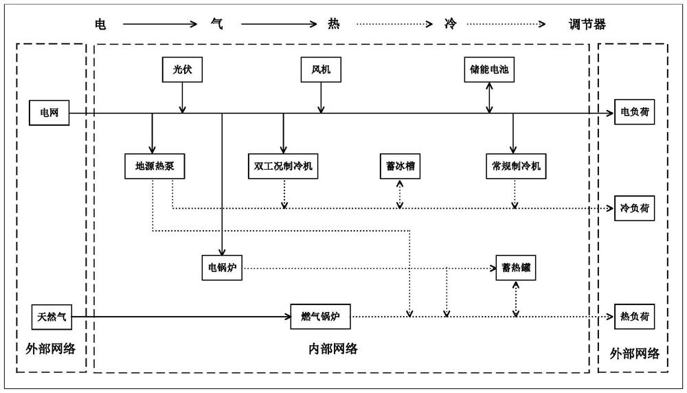
[0096] In some embodiments, the energy flow diagram of the integrated energy system is determined according to the energy data of the above-described integrated energy system. The flow chart of the so-called integrated energy system is based on the coupling characteristics of a variety of energy sources in the integrated energy system, and a flow chart of energy supply, transmission, exchange, storage, and storage is established.
[0097] Such as image 3 The energy flow diagram of the integrated energy system provided herein, referring to image 3 A variety of energy can be clearly known in the presence of each stage and the direction of energy transmission.
[0098] Flow maps are in the process of architectures, need to study the coupling characteristics of the integrated energy system, including economy, reliability, etc.; then study the operating characteristics of key equipment in the integrated energy system; finally study the transmission characteristics of the integrated energy system, including Power, thermal, natural gas and other energy forms.
[0099] In some embodiments, according to the energy flow map of the integrated energy system, the energy flow map model of the integrated energy system can be established in accordance with the multi-energy flow of the integrated energy system.
[0100] The general matrix equation expression of the multi-energy current calculation of the integrated energy system is as follows:
[0101]
[0102]
[0103]
[0104] In f e Represents power network equation; f represents thermal network equation; f g Represents natural gas network equation; △ P S △ Q S , △ φ D △ f SL , △ D, △ f , △ B s , △ B r △ f SL And ΔD represent imbalance; the remaining variables are the specific amount of status of power systems, thermal systems, and natural gas systems.
[0105] Optionally, from mathematics, these models can be described using the mathematical equations shown in:
[0106]
[0107] In the formula, the state quantity of the various energy networks involved can refer to the known amount and unknown amount of the energy network of the table 1, as follows:
[0108] Table 1
[0109]
[0110] In step S103, the integrated energy flow diagram model constraint condition is determined based on the integrated energy system flow graph model and constraint.
[0111] In some embodiments, it is necessary to consider the constraint conditions of the actual application scenario when designing and planning the integrated energy system for multi-body access.
[0112] Exemplary, this application describes the constraints of four aspects: energy balance constraint conditions, equipment physical constraints, investment quota constraints conditions, and energy interactive constraint conditions.
[0113] Optionally, it is necessary to constrain energy according to the energy supply and demand relationship of the energy, and the expression of energy balance constraints is:
[0114]
[0115] In P load (t) Indicates the electric load, H load (t) means hot load, L load (t) means cold load, P i (t) represents the power supply power of the device i; H m (t) represents the heating power of the device M; n (t) represents the cooling power of the device N.
[0116] Optionally, the device parameter constraint condition is required to be:
[0117]
[0118] In the form of Represents the minimum power of device J, Represents device J maximum power, P j (t) Indicates the real-time power of the device J at time t, SOC min Indicates the minimum of the remaining energy of the energy storage device accounts for the percentage of total capacity, SOC max Indicates that the remaining energy of the energy storage device accounts for the total capacity percentage, and SOC (T) represents the remaining energy of the energy storage device at time t at the total capacity percentage.
[0119] Optionally, it is also necessary to invest in the amount of investment quota based on the amount of funds investment, and the expression of the investment quota constraint is:
[0120]
[0121] In C inv Represents the initial investment of the integrated energy system; Maximum investment quota for integrated energy systems; unit_t Represents equipment unit capacity investment cost; Q unit_t Represents the planning capacity of the device; C LC Represents integrated energy.
[0122] Optionally, it is also necessary to perform energy interaction according to various energy exchange, and the expression of energy interaction constraint conditions is:
[0123]
[0124] In P grid Indicates exchange power between the grid and the integrated energy system, Indicates the upper limit of the exchange power between the power grid and the integrated energy system. Indicates the lower limit of exchange power between the power grid and the integrated energy system, P NG Indicates the amount of interaction between the natural gas network and the integrated energy system. Indicates the upper limit of the interaction between the natural gas network and the integrated energy system, Indicates the lower limit of the amount of interaction between the natural gas network and the integrated energy system.
[0125] In summary, combined with four constraint conditions common in the actual situation, the number of energy flow maps from physical energy transformation is optimized, and the energy efficiency of the integrated energy system can be improved.
[0126] In step S104, based on the energy flow map model of the integrated energy system and Efficiency, determine the evaluation index of the integrated energy system energy flow map model.
[0127] In some embodiments, in the actual energy transfer process, there is generally not only a form of energy in a system, but a mixture of various forms of energy. Therefore, in order to achieve the maximum effectiveness of energy efficiency, in the early stage of the design plan of the integrated energy system, in addition to the increase in physical energy conversion, it has been improved from the quality of physical energy conversion.
[0128] Exemplary, Indicates the ability of energy conversion to work, defined as the ability to convert to other energy forms when the system can reversibility into a given environment balance state. Efficiency is the system output Input Ratio. which is, The efficiency can reflect the magnitude of the "amount" of energy and the high and low "quality".
[0129] Optional, according to the integrated energy system characteristics, select different energy efficiency indicators, selected Efficiency As the integrated energy evaluation index, specific energy efficiency index analysis, see Table 2 Energy Efficiency Evaluation Index Comparative Analysis Table.
[0130] Table 2
[0131]
[0132] This application is only based on several Efficiency is an example to illustrate the consideration of physical energy transformation in quality, it is necessary to explain that the disclosure of this application is not described in detail. Efficiency, it is also possible to optimize the energy flow map model of the integrated energy system of the present application, which belongs to the concept of the technical solution of the present application. The above is respectively Efficiency is described in detail, including: cooling Efficiency, heating Efficiency, natural gas Efficiency and energy system effectiveness.
[0133] Exemplary, cooling The efficiency expression is:
[0134]
[0135] In the form of Refrigeration device Efficiency, W cE Indicates the power consumption of the refrigeration device W c middle Indicate the cooling amount Q c middle For the cooling capacity Q c The energy coefficient.
[0136] Exemplary, heating The efficiency expression is:
[0137]
[0138] In the form of Heating equipment Efficiency, W E Indicates the power consumption of the heating equipment W ε Q Q indicates that in the heating Q ε Q It is the energy coefficient of heat Q.
[0139] Exemplary, natural gas The efficiency expression is:
[0140]
[0141] In the form of Natural gas equipment Efficiency, W E Indicates the power generation E Q Indicate ε 0 E f Represents natural gas consumption E f middle ε 0 The energy coefficient of natural gas.
[0142] Exemplary, energy system The efficiency expression is:
[0143]
[0144] In the form of Indicate energy system Efficiency, W netE Indicate Indicate Refers to the refrigeration system Natural gas system
[0145] This step is introduced Efficiency As an evaluation index of energy efficiency, further optimization of the energy flow of the integrated energy system in terms of physical energy conversion in quality.
[0146] In particular, it is necessary to indicate that step S103 and step S104 do not logically contact and sequentially, that is, in the implementation process, step S103 can be implemented first, and then perform step S104, and then implement step S104, Then implement step 103.
[0147] In step S105, based on the integrated energy system energy flow map model constraint condition and the integrated energy system energy flow graph model evaluation index, the genetic algorithm is used to determine the model of energy efficiency improvement in the integrated energy system.
[0148] In some embodiments, in step S103 and step S104, the constraints and evaluation indexes of the integrated energy system flow graph model are optimized, and the devices involved in the model are running constraints and boundary constraints.
[0149] Optionally, the genetic algorithm can also be used to select energy efficiency to maximize equipment in optimized models. See the specific implementation process Figure 4 The genetic algorithm flowchart provided by an embodiment of the present application is provided. Specific steps are as follows:
[0150] Exemplary, based on the integrated energy system constraints and the integrated energy system evaluation index as the training data of the genetic algorithm, start training;
[0151] In step S201, start.
[0152] Code processing is performed on the various devices involved in the integrated energy system.
[0153] In step S202, the population is initialized.
[0154] The various devices that perform over-encoding process are used as population samples, and the population size and maximum iterative number T are determined, and the initialized species group S which is randomly generated is N, and the evolutionary generation counter T = 0 is set.
[0155] In step S203, the individual adaptation is calculated.
[0156] Calculate the individual fitness of the population S, the expression is In the formula, FIT is the minimum value of the individual adaptation function, indicating the highest application of individual;
[0157] In step S204, the calculation, crossover operation, and variation operation are selected.
[0158] The initialized population S is selected, and the sub-seed group q, which generates the initial species group S; the economic and environmental target value of the sub-generation population Q, and obtain the individual adaptation of the child population Q;
[0159] In step S205, it is determined whether or not it is the maximum fitness.
[0160] Until the number of iterations reaches the maximum number of iterative numbers, the individual is determined by the individual obtained during the evolution, and selects the maximum fitness individual as the optimal solution.
[0161] In step S206, end.
[0162] A further optimization model of energy efficiency improvement in the integrated energy system.
[0163] With the above-described genetic algorithm, it can measure the maximum design and planning plan for the energy efficiency of the integrated energy system.
[0164] In summary, the present application establishes a comprehensive energy system energy flow map model, which determines constraints and integrated energy sources of integrated energy systems in combination with energy conversion and energy conversion quality in the actual application scenario. The evaluation index of the system optimizes the integrated energy system energy flow map model. Finally, the genetic algorithm is used to optimize the integrated energy system flow graph model, and finally establish a model of energy efficiency in the integrated energy system.
[0165] The present application provides a method of maximizing energy efficiency, through comprehensive analysis of the characteristics of the integrated energy system, to build a method of energy efficiency to improve the integrated energy system model for actual conditions, and provide the design and planning of the integrated energy system. Guiding advice.
[0166] The present application provides an embodiment to verify the effectiveness and feasibility of the technical solution.
[0167] Preferred, selecting a multivariate region in my country as an example analysis area, because there is no investment increase, there is no investment quota constraint condition, and only various energy equipment for various energy equipment is collected and parameters. Analysis, and calculate the calculation of physical constraints of equipment, the calculation formula is:
[0168]
[0169] Wherein, the energy device parameters involved are shown in Table 3.
[0170] table 3
[0171]
[0172] Then, select the load data of the region in July 2020 as the training data, sampled once a day, a total of 15 data points. Its load data is shown in Table 4 Load data sample table.
[0173] Table 4
[0174]
[0175] Among them, based on load data table, calculation of energy balance constraint conditions and energy interactive constraints, the expression of energy balance constraints is:
[0176]
[0177] The expression of energy interactive constraints is:
[0178]
[0179] Based on the load data of various energy sources in Table 4, the cooling is calculated separately. Efficiency, heating Efficiency and natural gas effectiveness.
[0180] Cool cooling The efficiency expression is:
[0181]
[0182] Heating The efficiency expression is:
[0183]
[0184] natural gas The efficiency expression is:
[0185]
[0186] Based on the cooling cooling Efficiency, heating Efficiency and natural gas Efficiency, three kinds Efficiency is normalized and calculated to get the overall energy system effectiveness.
[0187] Energy system The efficiency expression is:
[0188]
[0189] Finally, the traditional planning plan and the planning plan of the present application technical plan are introduced. Efficiency Do data comparison, such as Figure 5 The efficiency data results are shown in the figure.
[0190] It will be apparent from the figure that the technical solution of the present application is significantly higher than that of the economic efficiency of the conventional solution, and the useful function of the integrated energy system can be more fully utilized. The effective effect of the energy efficiency of the integrated energy system of this application is remarkable.
[0191] It should be understood that the size of the sequence numbers in the above embodiments does not mean that the order of execution sequence, the execution order of each process should be determined in its function and inherent logic, without having to limit the implementation process of the present application embodiment.
[0192] A method corresponding to the energy efficiency of the integrated energy system according to the above embodiment, Image 6 A structural diagram of the integrated energy system energy efficiency lifting device provided in the present application embodiment is shown. For convenience of explanation, only the portions related to the present application embodiment are shown.
[0193] See Image 6 The integrated energy system energy efficiency lifting device in the present application may include: acquisition module 301, a model establishing module 302, a constraint condition module 303, an evaluation indicator module 304, and a calculated module 305.
[0194] Gets module 301 for obtaining energy data for the integrated energy system. Model establishment module 302 for establishing a comprehensive energy system flow graph model based on energy data of the integrated energy system. Constraint condition module 303 for determining the integrated energy system constraints based on the energy flow map model and constraints of the integrated energy system. Evaluation Index Module 304 for flow graph model based on integrated energy system Efficiency, determine the evaluation index of integrated energy system. The calculation module 305 is used to determine the model of energy efficiency in the integrated energy system energy system based on integrated energy system constraints and integrated energy system evaluation indicators.
[0195] In some embodiments, the acquisition module 301 is used to obtain all energy data in the system, including power energy, thermal energy, and natural gas energy, etc., is also used to obtain all supply, exchange, storage, consumption energy, equipment, installation, and operation. Power and other data.
[0196] In some embodiments, the model establishment module 302 is used to determine the energy flow diagram of the integrated energy system based on the energy data of the integrated energy system. It is also used to determine the energy flow map model of the integrated energy system based on the energy flow map of the integrated energy system.
[0197] In some embodiments, the constraint condition module 303 is used to determine the four aspect constraints, which are energy balance constraint conditions, equipment physical constraints, and investment quota conditions, and energy interactive constraint conditions, respectively.
[0198] In some embodiments, the evaluation indicator module 304 is used for: introducing cooling Efficiency, heating Efficiency, natural gas Efficiency and energy system Efficiency evaluation of energy efficiency on integrated energy systems.
[0199] It should be noted that the information interaction, execution process, and the like between the above-described apparatus / unit may refer to the method embodiment part of the technical effects, the specific function and the technical effects of the present application method, the specific function and the technical effects, which will be specifically referred to as the technical effects of the present application method embodiment. It will not be described again.
[0200]Those skilled in the art can clearly understand that in order to describe convenient and concise, only the various functional units, the division of the module, in the actual application, the above function is allocated by different functional units, The module is completed, that is, the internal structure of the device is divided into a different functional unit or module to complete all or part of the above described above. Each functional unit in the embodiment can be integrated into one processing unit, or each unit can be generated separately, or two or more units can be integrated into one unit, and the integrated unit can be used in both hardware. The form is implemented, or the form of software function unit can be implemented. In addition, each functional unit, the specific name of the module is also intended to distinguish between each other, and is not intended to limit the scope of the present application. The specific operation of the unit and module in the above system, can refer to the corresponding process in the foregoing method embodiment, and details are not described herein again.
[0201] The embodiment of this application also provides a terminal device, see Figure 7 The terminal setting 500 can include: at least one processor 510, a memory 520, and a computer program stored in the memory 520 and can operate on the at least one processor 510, the processor 510 performs the computer program. The steps in any of the above various method embodiments are realized, for example figure 2 Steps S101 to S105 in the illustrated embodiment are shown. Alternatively, the processor 510 implements the function of each of the modules / units in each of the various device embodiments, for example, Image 6 The functions shown in modules 301 to 305 are shown.
[0202] Exemplary, computer programs can be split into one or more modules / units, one or more modules / units are stored in memory 520 and is executed by processor 510 to complete this application. The one or more modules / units may be a series of computer blocks capable of completing a particular function, the program segment being used to describe the execution process of the computer program in the terminal device 500.
[0203] Those skilled in the art will appreciate that Figure 7 It is only an example of a terminal device, and does not constitute a limit for the terminal device, which may include more or fewer components, or a combination of certain components, or different components, such as input and output devices, network access devices. Bus, etc.
[0204] The processor 510 can be a central processing unit (CPU), as well as other universal processors, Digital Signal Processor, DSP, dedicated integrated circuit (Application Specific Integrated Circuit, ASIC), ready-made Field-Programmable Gate Array, FPGA or other programmable logic devices, separate doors or transistor logic devices, discrete hardware components, and the like. The general purpose processor can be a microprocessor or the processor can also be any conventional processor or the like.
[0205] The memory 520 can be the internal storage unit of the terminal device, or an external storage device of a terminal device, such as a plug-in hard disk, a smart media card, SMC, a secure number (Secure Digital, SD) card, flash card (Flash Card), etc. The memory 520 is used to store other programs and data required for the computer program and terminal devices. The memory 520 can also be used to temporarily store data that has been output or will output.
[0206] The bus can be an industrial standard architecture (ISA) bus, an external device interconnect (PCI) bus, or an Extendedustry Standard Architecture, EISA boss. The bus can be divided into an address bus, a data bus, a control bus, and the like. In order to facilitate the presentation, the bus in the drawings of the present application does not limit only one bus or a type of bus.
[0207] The effective energy efficiency of the integrated energy system provided herein can be applied to the computer, wearable equipment, in-vehicle equipment, tablets, laptops, netbooks, personal digital assistants, PDA, enhanced reality (Augment Reality) On terminal devices such as virtual reality, VR), mobile phones, etc., this application embodiment does not limit the specific type of end device.
[0208] The present application embodiment also provides a computer readable storage medium that stores a computer program that implements various embodiments of the above-described integrated energy system energy efficiency when executed by the processor. The steps are in the steps.
[0209] The present application example provides a computer program product, when the computer program product is running on the mobile terminal, making the step of implementing the mobile terminal to implement the energy efficiency of the above-mentioned energy system energy efficiency increase.
[0210] The integrated unit can be stored in a computer readable storage medium if implemented in the form of a software functional unit and is used as a stand-alone product. Based on this, the present application implements all or partial flow in the above embodiment method, which can be done by a computer program to instruct the hardware, and the computer program can be stored in a computer readable storage medium, the computer program When executed by the processor, the steps of the various method embodiments described above can be realized. Wherein, the computer program includes a computer program code that can be a source code form, an object code form, an executable file, or some intermediate form. The computer readable medium can include: capable of carrying computer program code to any entity or device, recording medium, computer memory, read-only memory (ROM, READ-ONLY MEMORY), random access memory (RAM, Randomaccess Memory), electrical carrier signal, telecommunications signal, and software distribution media. For example, a U disk, a mobile hard disk, a disk, or an optical disk, or the like. In some jurisdictions, according to legislation and patent practice, computer readable media cannot be a carrier signal and a telecommunications signal.
[0211] In the above embodiment, each of the descriptions of each of the embodiments have each other, and a portion not described in detail or described in an embodiment, see a related description of other embodiments.
[0212] One of ordinary skill in the art will appreciate that the unit and algorithm steps described herein will be used in the combination of electronic hardware, or computer software and electronic hardware. These functions are executed in hardware or software, depending on the specific application and design constraints of the technical solution. Professional technicians can use different methods to implement the described functions for each particular application, but this implementation should not be considered exceeded the scope of the present application.
[0213] In the embodiments provided herein, it should be understood that the disclosed device / network device and method can be implemented in other ways. For example, the device / network device embodiment described above is merely schematic, for example, the division of the module or unit is only one logical function division, and there may be additional division methods, such as a plurality of units. Or components can be combined or can be integrated into another system, or some features can be ignored, or not executed. On the other hand, the coupling or direct coupling or communication connection of the displayed or discussed may be an electrical, mechanical or other form.
[0214] The unit as the separation member may be or may not be physically separated, and the components displayed as the unit may be or may not be a physical unit, i.e., in one place, or can also be distributed to a plurality of network elements. The object of the present embodiment can be implemented in accordance with the actual needs to select some or all units.
[0215] The above embodiments are intended to illustrate the technical solutions of the present application, and will not limit their detailed description of the present application, however, those skilled in the art will appreciate that The technical solution described in Example is modified, or part of the technical features are equivalent to alternative; and these modifications or replacements do not allow the nature of the corresponding technical solution from the spirit and scope of the technical solutions of the present invention, it should be included. Within the protection of this application.

PUM

no PUM

Description & Claims & Application Information

We can also present the details of the Description, Claims and Application information to help users get a comprehensive understanding of the technical details of the patent, such as background art, summary of invention, brief description of drawings, description of embodiments, and other original content. On the other hand, users can also determine the specific scope of protection of the technology through the list of claims; as well as understand the changes in the life cycle of the technology with the presentation of the patent timeline. Login to view more.
Why Eureka
Try Eureka