Environmental test box for controlling high and low temperature alternation
An environmental test chamber, high and low temperature technology, applied in the field of environmental test chambers, can solve the problems of difficulty in improving the control accuracy of equipment, samples near the window, and the influence of the test environment, and achieve the effect of avoiding the deterioration of the visual effect.
- Summary
- Abstract
- Description
- Claims
- Application Information
AI Technical Summary
Problems solved by technology
Method used
Image
Examples
Embodiment 1
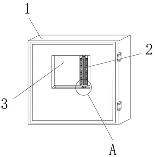
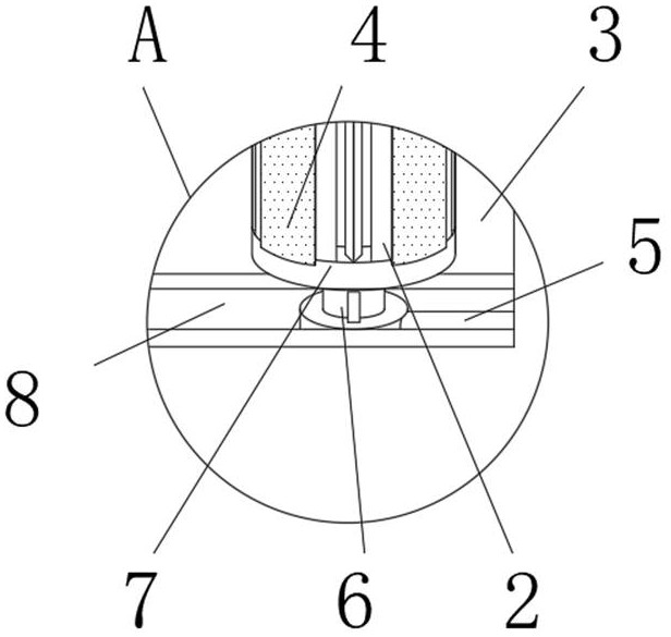
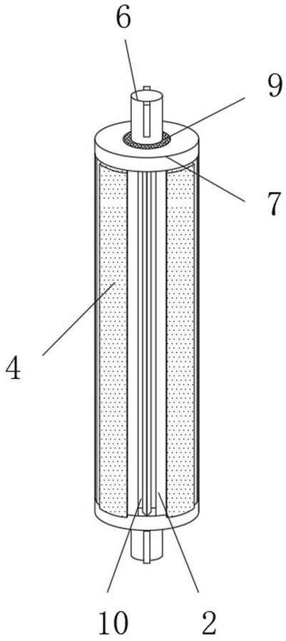
[0032] Such as Figure 1-2 As shown, an environmental test chamber for controlling high and low temperature alternation includes a chamber body and a chamber door 1, a window 3 is embedded in the middle of the chamber door 1, a chute 8 is provided on the edge of the window 3, and one end of the chute 8 is fixed A drive rod 5 is installed, and one end of the drive rod 5 away from the chute 8 is movably connected with an extension rod 6. The outer end surface of the extension rod 6 is sleeved with a cleaning device 2, and the cleaning device 2 is attached to the surface of the window 3. There is a temperature sensing device that drives the extension rod 6 to move. The side end surface of the cleaning device 2 is fixedly embedded with multiple sets of cleaning layers 4. The two ends of the cleaning device 2 are fixedly connected with a rotating ring 7, and the middle part of the rotating ring 7 is elastically embedded with a nut 9. The side end surface of the extension rod 6 is p...
Embodiment 2
[0036] On the basis of Example 1, as Figure 1-4As shown, the temperature sensing device includes a temperature sensing cavity 12 and a temperature sensing layer 13, the temperature sensing layer 13 is arranged inside the cleaning device 2, and the two ends of the temperature sensing layer 13 are connected to each other in rotation with the cleaning device 2, and the temperature sensing layer 13 is connected to the cleaning device 2. A temperature sensing cavity 12 is opened between the devices 2 .
[0037] Such as Figure 1-4 As shown, the middle part of the temperature-sensing layer 13 is embedded with a partition plate 16, and the extension rod 6 is flexibly connected to the inside of the temperature-sensing layer 13. A sealed cavity 15 is formed between the extension rod 6 and the temperature-sensing layer 13, and the inside of the sealed cavity 15 is filled with There is a temperature-sensing medium, and the side end surface of the cleaning device 2 is provided with an a...
Embodiment 3
[0049] On the basis of Example 2, such as Figure 1-11 As shown, the resisting rod 24 is movably embedded inside the temperature-sensing layer 13, and the temperature-sensing layer 13 is provided with a movable groove matching the resisting rod 24. One end of the resisting rod 24 is fixedly connected with a spring 27, and the spring 27 is away from the resisting rod 24. One end of one end is elastically connected with an adjustment plate 29, and the adjustment plate 29 is slidably connected to the inside of the movable groove through a limit slider. , the adjustment knob 28 is connected to the temperature-sensing layer 13 in rotation, the position of the adjustment plate 29 inside the movable groove can be controlled by turning the adjustment knob 28, and then the elastic travel of the control spring 27 is controlled, thereby controlling the elastic force of the rod 24, thereby controlling the The stroke threshold value of the thermally deformable metal 25 is controlled, so th...
PUM
 Abstract
Description
Claims
Application Information
 - R&D
- Intellectual Property
- Life Sciences
- Materials
- Tech Scout
- Unparalleled Data Quality
- Higher Quality Content
- 60% Fewer Hallucinations
Browse by: Latest US Patents, China's latest patents, Technical Efficacy Thesaurus, Application Domain, Technology Topic, Popular Technical Reports.
© 2025 PatSnap. All rights reserved.Legal|Privacy policy|Modern Slavery Act Transparency Statement|Sitemap|About US| Contact US: help@patsnap.com


