Inverse proportion pressure reducing valve

A pressure reducing valve and inverse proportional technology, applied in the direction of fluid pressure actuators, servo motor components, mechanical equipment, etc., can solve the problems of low control accuracy, achieve the effects of improving control accuracy, improving stability, and mitigating impact

Pending Publication Date: 2021-12-03
ZHEJIANG STRONGER HYDRAULIC
View PDF1 Cites 0 Cited by
  • Summary
  • Abstract
  • Description
  • Claims
  • Application Information

AI Technical Summary

Problems solved by technology

[0005] The purpose of the present invention is to address the above problems in the prior art, and propose an inverse proportional pressure reducing valve, which solves the problem of low control precision of the existing inverse proportional pressure reducing valve

Method used


Image

  • Inverse proportion pressure reducing valve
  • Inverse proportion pressure reducing valve
  • Inverse proportion pressure reducing valve

Examples


Embodiment 1

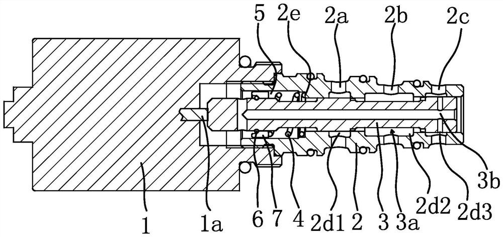
[0031] Such as figure 1 As shown, an inverse proportional pressure reducing valve includes a valve body 2, a valve core 3 located in the valve body 2 that can slide axially, and a spring 4 located between the valve body 2 and the valve core 3, and one end of the valve body 2 is connected with an electromagnetic Iron 1, specifically, one end of the spool 3 is fixed to the electromagnet 1 through threads, and the spool 3 is provided with a through hole for the installation of the spool 3. When the spool 3 is installed in the valve body 2, the valve body 2 A spring cavity 5 is formed between one end close to the electromagnet 1 and the valve body 2. The spring 4 is installed in the spring cavity 5 and the two ends respectively act on the valve body 2 and the valve core 3. More specifically, the electromagnet 1 is provided with There is a push rod 1a, and the electromagnet 1 transmits power to the valve core 3 through the push rod 1a, thereby forming a thrust force opposite to the...


PUM


Abstract

The invention provides an inverse proportion pressure reducing valve, and belongs to the technical field of valves. The problem that an existing inverse proportion pressure reducing valve is low in control precision is solved. The inverse proportion pressure reducing valve comprises a valve body and a valve element which is located in the valve body and can axially slide, an input oil port; an output oil port and an oil drainage port are sequentially formed in the circumferential face of the valve body in a penetrating mode; a communication groove is arranged on the circumferential face of the valve element; a spring which enables the valve element to slide and enables the communication groove to be jointly communicated the input oil port and the output oil port is arranged between the valve body and the valve element; one end of the valve body is connected with an electromagnet used for pushing the valve element to overcome spring force; the electromagnet can form thrust opposite to the spring force acting on the valve element; and the axial stress area of the valve element on the side, away from the electromagnet, of the communication groove is larger than the axial stress area of the valve element on the side, close to the electromagnet, of the communication groove. The inverse proportion pressure reducing valve provided by the invention has the advantages of good stability, high control precision and the like.

Description

technical field [0001] The invention belongs to the technical field of valves, and relates to a pressure reducing valve, in particular to an inverse proportional pressure reducing valve. Background technique [0002] Electro-hydraulic mixing proportional control technology is more and more widely used in construction machinery, such as the precise control of flow, pressure and power of hydraulic pumps in construction machinery through electric proportional pressure control, thereby reducing energy consumption and improving operating comfort sex etc. [0003] Some people in the market have proposed a proportional pressure reducing valve with the Chinese application number CN201621243996.X, an automobile automatic transmission and an automobile. The proportional pressure reducing valve includes a slide valve assembly, which includes a slide valve sleeve of a hollow mechanism 1. The pressure reducing valve spool set in the spool valve sleeve and the elastic component against t...

Claims


Application Information

Patent Timeline
Patent Type & Authority Applications(China)
IPC IPC(8): F15B13/02
CPCF15B13/025
Inventor 李童叶鹏飞李玮斌
Owner ZHEJIANG STRONGER HYDRAULIC
Why Eureka
Try Eureka