Gas leakage detection and argon blowing flow correction method of argon blowing inlet pipeline of ladle ventilating upper nozzle block
A technology of argon blowing flow rate and air intake pipeline, which is applied in the field of gas leakage detection and argon blowing flow correction of the argon blowing intake pipeline of the ventilating upper nozzle block of the ladle. The effect of argon metallurgy, reducing the weight of inclusions, and reducing the amount of molten steel pouring
- Summary
- Abstract
- Description
- Claims
- Application Information
AI Technical Summary
Problems solved by technology
Method used
Image
Examples
Embodiment 1
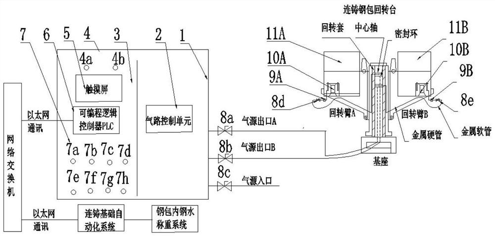
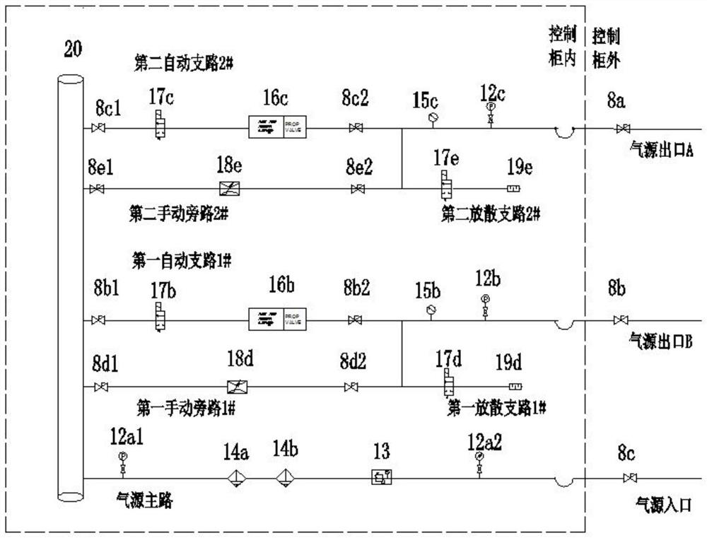
[0035] Such as Figure 1-Figure 3 Shown is an argon-blowing air intake pipeline of a ventilating upper nozzle block of a ladle and its air leakage detection and correction method. , Measure the air leakage. Under the condition of small air leakage, you can use not to deal with the air leakage point, and set the argon blowing flow determined through creative labor + measured air leakage as automatic or manual argon blowing control flow.
[0036] The ladle air-permeable upper nozzle block described in this embodiment refers to the ladle microporous ceramic rod air-permeable upper nozzle seat brick disclosed in Chinese patent CN111774560A.
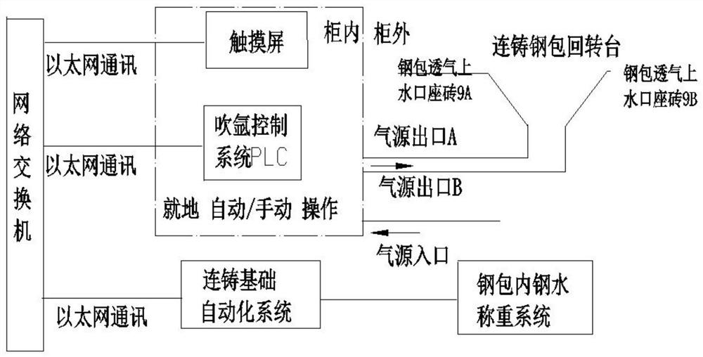
[0037] Such as figure 1 with image 3 As shown, the argon blowing control system of the present invention includes a touch screen 5, a programmable logic controller PLC 6, a signal lamp 4, a continuous casting basic automation system and a molten steel weighing system in a ladle. The programmable logic controller PLC is respectively connec...
Embodiment 2
[0065] The ventilating upper nozzle seat brick of the ladle described in this embodiment is the diffuser ring ventilating nozzle seat brick of the ladle in the Chinese patent CN109732074A.
[0066] When the argon blowing argon blowing air intake line of the ladle ventilating upper nozzle block described in this embodiment and its air leakage detection and correction method are applied to the argon blowing control of the ladle ventilating upper nozzle block with an average steel output of 135 tons, through creative labor Simulation research and application practice verify the various stages of the continuous casting ladle pouring process and the optimal argon blowing flow rate, specifically:
[0067] S1. In the early and mid-stage of continuous casting ladle pouring process, the best stage of inclusion removal rate and the best argon blowing flow rate: the weight of remaining steel in the ladle after the ladle starts pouring and normal downflow is 2 / 3 of the weight of molten ste...
Embodiment 3
[0076]The argon blowing inlet pipeline in this embodiment is the same as that in Embodiment 1. The gas leakage detection and argon blowing flow correction method of the argon blowing inlet pipeline of the ladle breathable upper nozzle block in this embodiment includes the following steps:
[0077] (1) Carry out air leakage detection on the argon blowing inlet pipeline, and measure the air leakage amount: use the argon blowing control system to manually open the third manual ball valve 8c at the inlet of the gas source, the first manual ball valve 8a at the outlet A of the gas source, The second manual ball valve 8b at the outlet B of the gas source manually closes the manual limit ball valve 8d on the air intake pipe of the ladle ventilating upper nozzle seat brick laid by the rotary arm A of the continuous casting ladle rotary table and the ladle ventilating upper layer laid by the rotary arm B The manual limit ball valve 2 8e on the intake pipe of the nozzle seat brick. On t...
PUM
 Abstract
Description
Claims
Application Information
 - R&D
- Intellectual Property
- Life Sciences
- Materials
- Tech Scout
- Unparalleled Data Quality
- Higher Quality Content
- 60% Fewer Hallucinations
Browse by: Latest US Patents, China's latest patents, Technical Efficacy Thesaurus, Application Domain, Technology Topic, Popular Technical Reports.
© 2025 PatSnap. All rights reserved.Legal|Privacy policy|Modern Slavery Act Transparency Statement|Sitemap|About US| Contact US: help@patsnap.com


