
A Compensation Method for Roller's Transverse Position Error

A technology of traversing position and compensation method, which is applied in the direction of metal rolling, metal rolling, metal rolling stand, etc., can solve the problems of no obvious improvement, asymmetric bending force, slow moving speed, etc., and achieve no complicated Calculation process, improvement of product quality, and simple calculation form

Active Publication Date: 2022-07-29
YANSHAN UNIV +1
View PDF10 Cites 0 Cited by
  • Summary
  • Abstract
  • Description
  • Claims
  • Application Information

AI Technical Summary

Problems solved by technology

After investigation, it was found that although the existing formula for calculating the preset movement distance of the roll traverse can accurately calculate the value of the movement distance, the movement speed of the hydraulic cylinder is slow due to the up and down execution of the roll traverse, or the movement speed of the hydraulic cylinder is slow due to the roll traverse up and down. The action error of the execution hydraulic cylinder, the measurement error of the detection unit of the plate shape closed-loop feedback control system, and the installation accuracy error of the rolling mill itself make the calculated preset moving distance of the roll traverse and the actual roll traverse up and down execution hydraulic cylinder. There is a deviation in the moving distance, resulting in an asymmetrical bending force acting on the strip, which in turn leads to uneven distribution of the strip shape
[0005] After visiting many tandem cold rolling mills, it is found that most of the tandem cold rolling mills will have poor shape due to the deviation between the preset movement distance of the roll traverse and the actual movement distance of the roll traverse up and down execution hydraulic cylinders question
Technicians in some tandem cold rolling mills tried to solve this problem by changing the rolling force and the length of the work roll body, but none of them had obvious improvement effects, and it would easily lead to more serious strip product quality problems

Method used


Image

  • A Compensation Method for Roller's Transverse Position Error
  • A Compensation Method for Roller's Transverse Position Error
  • A Compensation Method for Roller's Transverse Position Error

Examples


Embodiment Construction

[0044] The present invention will be further described below with reference to the accompanying drawings and embodiments.

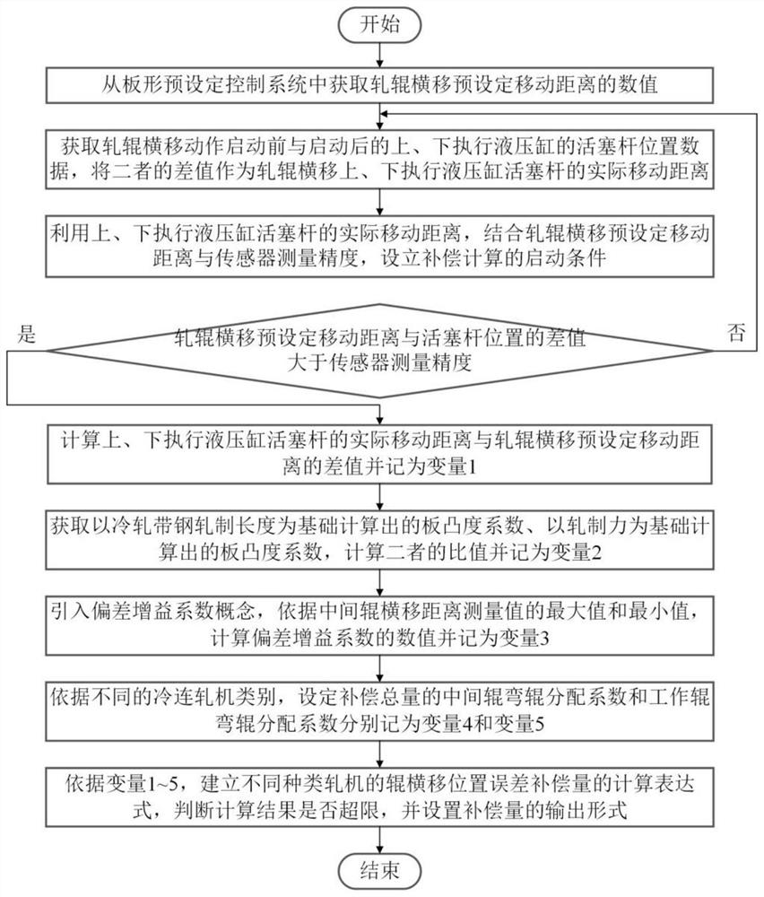
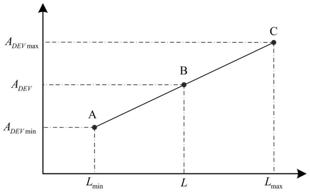
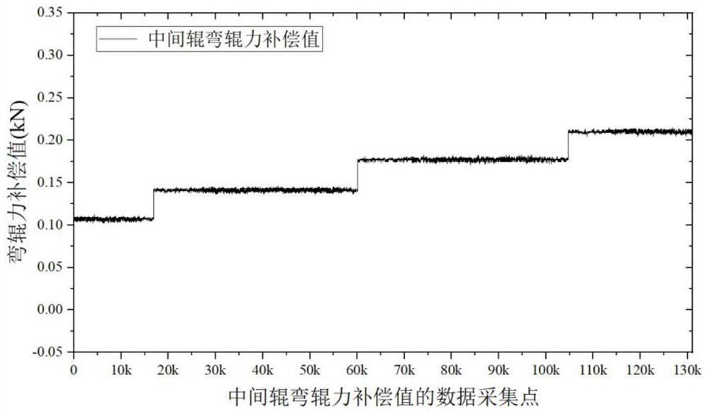
[0045] The core idea of ​​the method of the present invention includes: 1. Obtaining the preset moving distance of the roll traverse movement, and determining the opening condition of the compensation calculation according to the relationship between the position of the piston rod of the hydraulic cylinder for performing the roll traverse movement up and down and the measurement accuracy of the sensor; 2. According to the difference between the preset moving distance of the roll transverse movement and the actual movement distance of the hydraulic cylinder when the roll transverse movement is performed up and down, the plate crown coefficient calculated on the basis of the rolling length of the cold-rolled strip and the rolling force as the basis The calculated plate crown coefficient and deviation gain coefficient determine the calculation expression of t...


PUM


Abstract

The invention discloses a method for compensating roll lateral displacement position error, and relates to the technical field of metallurgical rolling. First of all, the present invention considers the phenomenon of uneven distribution of bending force on the surface of cold-rolled strip due to the deviation between the preset moving distance of the roll traverse and the actual movement distance of the hydraulic cylinder for the upper and lower execution of the roll traverse. The roll force can be evenly applied to the surface of the cold-rolled strip; secondly, according to the existing rolling regulations and real-time data collection, the compensation method can be applied to each stand of the four-high and six-high tandem cold rolling mills, and has a wide range of advantages. Thirdly, this method can eliminate the deviation between the preset moving distance of the roll traverse and the actual moving distance of the hydraulic cylinder for the upper and lower execution of the roll traverse, and improve the quality of cold-rolled strip products. Finally, the calculation form of this method is The method can be quickly transformed into the form required by the computer programming language and applied to the automatic control system for the shape of the cold-rolled strip.

Description

technical field [0001] The invention relates to the technical field of metallurgical rolling, in particular to a method for compensating roll lateral displacement position error. technical background [0002] At present, the shape automatic control system of cold-rolled strip is generally composed of two parts: the shape preset control system and the shape closed-loop feedback control system. The flatness preset control system is that the flatness control computer pre-sets the adjustment amount of the flatness control mechanism and outputs it to the actuator according to the selected target shape before the strip enters the roll gap. The shape closed-loop feedback control system is to calculate the deviation between the actual shape and the target shape with the measured shape signal of the shape roll as the feedback information under stable rolling conditions, and to eliminate these shapes through the feedback calculation model analysis and calculation. The adjustment amou...

Claims


Application Information

Patent Timeline
Patent Type & Authority Patents(China)
IPC IPC(8): B21B37/28B21B31/20
CPCB21B37/28B21B31/20
Inventor 王鹏飞李旭金树仁孙杰黄华贵孙静娜华长春李文田张殿华张昭张欣宋章峰
Owner YANSHAN UNIV
Learn More