
Universal tool clamp for heat setting of metal intravascular stent
A technology of vascular stents and tooling fixtures, which is applied in the field of medical devices, can solve the problems of vascular stent damage, high friction, and inability to meet the needs of stents with different diameters, and achieve the effects of convenient operation, simple production, and convenient heat setting treatment
- Summary
- Abstract
- Description
- Claims
- Application Information
AI Technical Summary
Problems solved by technology
Method used
Image

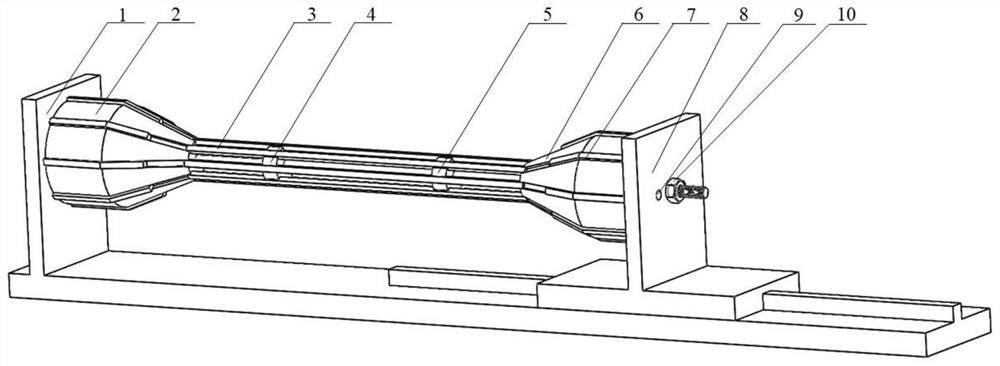
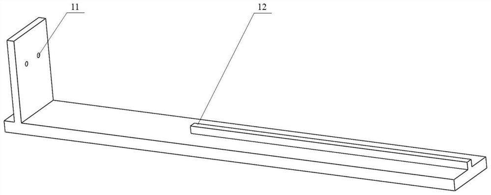
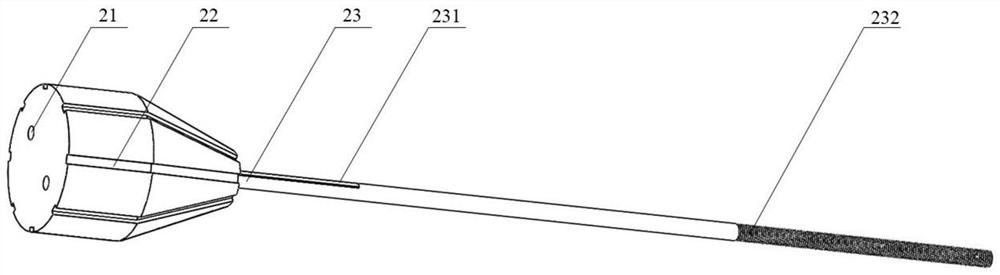
Examples
specific Embodiment approach
[0065] 1. Fix the fixed base 1 and the fixed tapered support block 2 together through the interference fit of the pin hole 11, pin hole 21 and pin 9 provided thereon;
[0066] 2. Fix the sliding tapered support block 6 and the sliding base 8 together through the interference fit of the pin hole 63, pin hole 82 and pin 9 provided thereon;
[0067] 3. Divide 16 pole limit bars 7 of the same size into two groups, one group of 8 pieces, and the two groups are respectively installed on the guide groove 22 on the fixed tapered support block 2 and the sliding tapered support in the way of magnetic adsorption. In the guide groove 61 on the block 6;
[0068] 4. Mount the 1 / 4 of the left ends of the eight struts 3 in the slot 41 on the positioning strut support frame 4 by magnetic adsorption, and install the 1 / 4 of the right ends on the support rod support frame 5 by magnetic adsorption. in slot 51;
[0069] 5. The whole step 4 is composed of 8 struts 3, positioning strut support fram...
PUM
 Abstract
Description
Claims
Application Information