Metal plate welding clamp

A welding fixture and sheet metal technology, applied in the field of sheet metal processing, can solve the problems of affecting welding quality, lack of hardness, and low practicability, and achieve the effect of convenient and uniform clamping, reducing scratch damage and deformation

Pending Publication Date: 2022-03-01
尹涛
View PDF1 Cites 0 Cited by
  • Summary
  • Abstract
  • Description
  • Claims
  • Application Information

AI Technical Summary

Problems solved by technology

[0005] 1. This type of fixture for sheet metal welding uses the movement of the left and right sets of fixtures to achieve clamping of the sheet metal. This clamping mechanism is only suitable for the clamping of a single piece of sheet metal and the welding of its own gaps, and cannot be used The clamping and welding of multiple sheet metals has low practicability; because the sheet metal body is thin and the hardness is lacking, when the clamping block of this structure clamps the sheet metal, the contact area with the sheet metal is small. When the two sides of the sheet metal are squeezed by two clamping blocks, the two side frames of the sheet metal are not completely in contact with the clamping blocks, so they are locally stressed, which easily causes deformation of the sheet metal during the clamping process and affects the welding quality;
[0006] 2. This kind of fixture used for sheet metal welding is only to simply fix the sheet metal, but in actual use, the general fixture clamping mechanism just fixes the sheet metal body, and a reverse force will be generated during welding. The fixed force phase is the top, and the long-term processing will make the fixing mechanism loose, and the welding work cannot be carried out effectively, wasting a lot of time, and there are certain safety hazards

Method used


Image

  • Metal plate welding clamp
  • Metal plate welding clamp
  • Metal plate welding clamp

Examples


Embodiment Construction

[0028] The following will clearly and completely describe the technical solutions in the embodiments of the present invention with reference to the accompanying drawings in the embodiments of the present invention. Obviously, the described embodiments are only some, not all, embodiments of the present invention. Based on the embodiments of the present invention, all other embodiments obtained by persons of ordinary skill in the art without making creative efforts belong to the protection scope of the present invention.

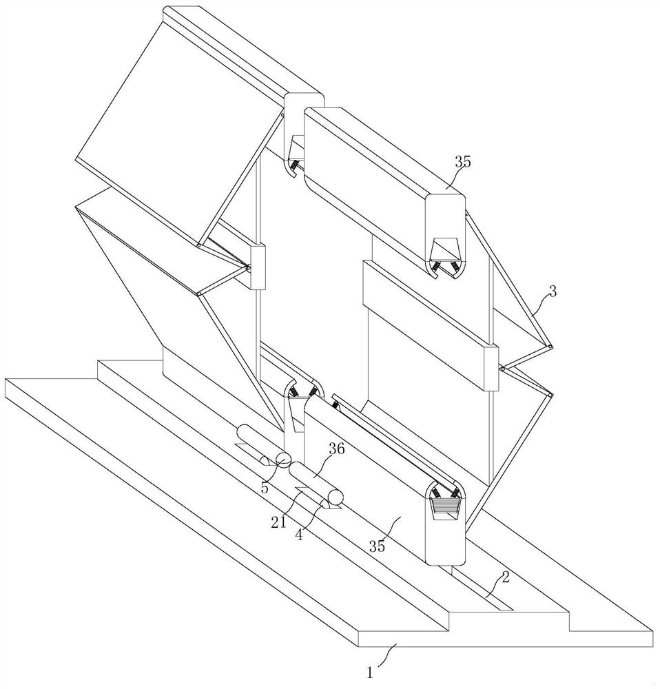
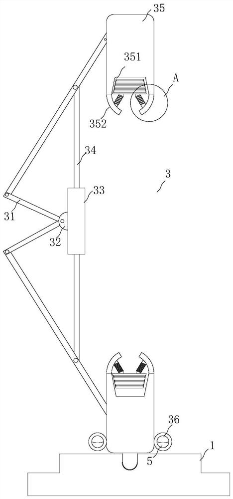
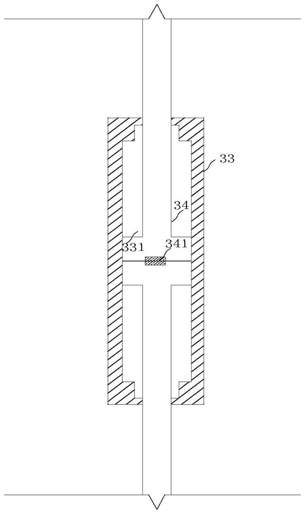
[0029] see Figure 1 to Figure 6 , the present invention provides a technical solution:

[0030] A sheet metal welding fixture, such as figure 1 and Figure 4 As shown, it includes a base 1, the base 1 has a convex structure, and the middle position of the upper end of the base 1 is provided with a slide rail 2, and the inside of the slide rail 2 is slidably connected with two sets of clamping mechanisms 3, the two sets of The clamping mechanism 3 is symmet...


PUM


Abstract

The invention relates to the technical field of sheet metal machining, in particular to a sheet metal welding clamp which comprises a base, the base is of a convex structure, a sliding rail is arranged in the middle of the upper end of the base, two clamping mechanisms are slidably connected into the sliding rail, and the two clamping mechanisms are symmetrical front and back and are distributed in opposite structures; the clamping mechanism comprises two groups of movable plates, a semicircular clamping piece, a vertical frame, a supporting rod and a clamping frame, the movable plates are L-shaped, the joints of the movable plates are hinged through a hinge shaft, and the two groups of movable plates are movably connected up and down. According to the metal plate clamping device, a plurality of metal plates can be conveniently aligned and uniformly stressed and clamped, external scratches, damage and deformation of the metal plates are reduced, meanwhile, simple adjustment can be conducted according to the heights of the metal plates, the metal plates can be rapidly adjusted and clamped, the situation that the clamping mechanism is loosened or the position is affected due to long-time machining is reduced, welding work can be effectively conducted, and the working efficiency is improved; and the probability of certain potential safety hazards is reduced.

Description

technical field [0001] The invention relates to the technical field of sheet metal processing, in particular to a sheet metal welding fixture. Background technique [0002] In the sheet metal processing process, welding is a very important process, and in order to stabilize the position of the sheet metal parts during sheet metal welding, it is often achieved by means of fixtures. [0003] The existing patent (notification number: CN210360079U) is a fixture for sheet metal welding, including an operating table, the upper surface of the operating table is provided with a fixed base and a slide rail, and the fixed base is located on one side of the slide rail. The outer surface of the slide rail is provided with a moving base. The utility model discloses a fixture for sheet metal welding. Through the setting of the slide rail, the slide rail can make the fixture slide and can be used for workpieces of various sizes. It can be fixed. Through the setting of the lifting rod, the...

Claims


Application Information

Patent Timeline
IPC IPC(8): B23K37/04
CPCB23K37/0443
Inventor 尹涛朱忠祥
Owner 尹涛
Why Eureka
Try Eureka