Multilayer high power nano friction generator

A friction generator and nano-friction technology, which is applied in the direction of friction generators, layered products, metal layered products, etc., can solve the problem of low output power of friction generators

Active Publication Date: 2014-03-26
NEWNAGY TANGSHAN
View PDF4 Cites 43 Cited by
  • Summary
  • Abstract
  • Description
  • Claims
  • Application Information

AI Technical Summary

Problems solved by technology

[0004] The technical problem solved by the present invention is: to overcome the defect of low output power of existing friction generators, and to provide a multi-layer high-power nano friction generator, which uses conductive (metal) materials and polymer friction to generate an induced electric field, thereby self-powered

Method used


Image

  • Multilayer high power nano friction generator
  • Multilayer high power nano friction generator
  • Multilayer high power nano friction generator

Examples


Embodiment 1

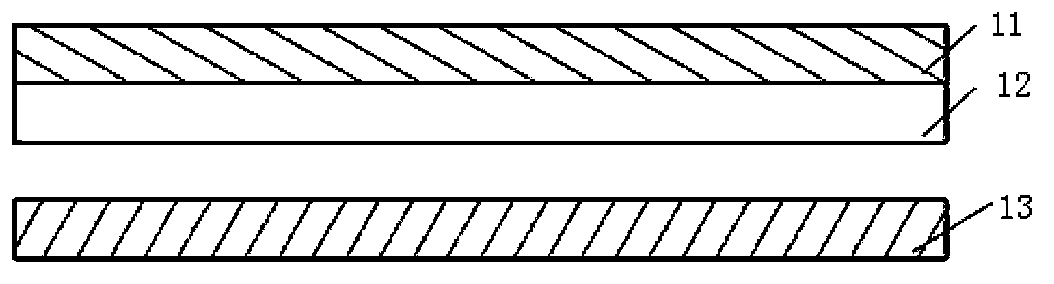
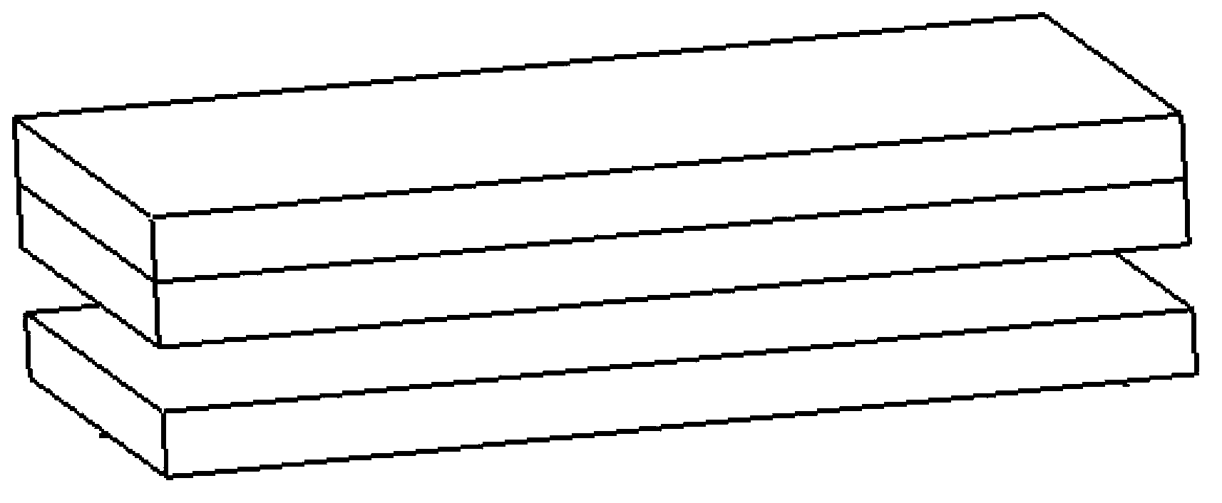
[0071] Such as figure 1 with 2 As shown, the nano triboelectric generator in this embodiment is a non-transparent multi-layer film type, with a size of 4.5 cm×1.2 cm and a total thickness of about 250 μm. The triboelectric generator includes an electrode 11 , a polymer insulating layer 12 and a triboelectrode 13 which are stacked in sequence.

[0072] A rectangular (4.5 cm×1.2 cm) polyimide film (thickness 125 μm, DuPont 500HN) is used as the polymer insulating layer 12 . The polymer insulating layer 12 is provided with a micro-nano concave-convex structure 6 with a raised height of 150 nm on one surface (see Figure 7 with 8 ), and a gold film with a thickness of 100 nm is plated on the other surface, and the gold film is the electrode 11 .

[0073] Copper foil with a thickness of 100 μm is used as the triboelectrode 13, and the two surfaces of the copper foil are polished with fine sandpaper to provide irregular micro-nano concave-convex structures with a protrusion heig...

Embodiment 2

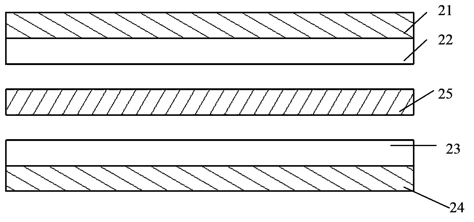
[0077] Such as image 3 with Figure 4 As shown, the nano triboelectric generator in this embodiment is a non-transparent multi-layer film type, with a size of 4.5 cm×1.2 cm and a total thickness of about 500 μm. The triboelectric generator comprises a first electrode 21 , a first high molecular polymer insulating layer 22 , a friction electrode 25 , a second high molecular polymer insulating layer 23 and a second electrode 24 which are sequentially stacked.

[0078] A rectangular (4.5 cm×1.2 cm) polyimide film (thickness 125 μm, DuPont 500HN) is used as the first polymer insulating layer 22 and the second polymer insulating layer 23 . The first high molecular polymer insulating layer 22 and the second high molecular polymer insulating layer 23 are respectively provided with a micro-nano concave-convex structure with a raised height of 150nm on one surface, and an aluminum film with a thickness of 100nm is plated on the other surface, and the aluminum thin film is are the fi...

Embodiment 3

[0083] The structure of this embodiment is basically the same as that of Embodiment 2, the only difference is that there is no micro-nano concave-convex structure on the two surfaces of the friction electrode 25, and the material used for the first polymer insulating layer 22 is polyoxymethylene. Using the same method as Example 2 to test, the maximum output voltage and current signal of friction generator 3# reached 50V and 10μA respectively.


PUM

PropertyMeasurementUnit
heightaaaaaaaaaa
heightaaaaaaaaaa
heightaaaaaaaaaa

Abstract

The invention discloses a nano friction generator which comprises an electrode, a polymer insulating layer and a friction electrode, wherein the electrode, the polymer insulating layer and the friction electrode are sequentially overlapped. A micro nano concave convex structure is arranged on at least one surface in two surfaces, which are oppositely arranged, of the polymer insulating layer and the friction electrode. The electrode and the friction electrode are voltage and current output electrodes of the friction generator. According to the invention, the friction of a conductive (metal) film and polymer is used; and metal is easy to lose electrons, thus the friction electrode and the polymer insulating layer form an induction electric field.

Description

technical field [0001] The invention relates to a friction generator, in particular to a multilayer high-power nanometer friction generator using conductive (metal) materials as friction electrodes. Background technique [0002] With the continuous improvement of modern living standards and the accelerated pace of life, self-generating equipment with convenient application and low dependence on the environment has emerged. Existing self-generating devices typically exploit the piezoelectric properties of materials. For example, in 2006, Wang Zhonglin, a professor at the Georgia Institute of Technology in the United States, successfully converted mechanical energy into electrical energy at the nanoscale, and developed the world's smallest generator - a nanogenerator. The fundamental principle of nanogenerators is that when nanowires (NWs) are dynamically stretched under an external force, piezoelectric potentials are generated in the nanowires, and corresponding transient cu...

Claims


Application Information

Patent Timeline
Patent Type & Authority Applications(China)
IPC IPC(8): H02N1/04
CPCH02N1/04B32B15/04
Inventor 范凤茹徐传毅刘军锋
Owner NEWNAGY TANGSHAN
Why Eureka
Try Eureka