
Hybrid frequency-driven three-dimensional ellipse turning method
A three-dimensional, mixed frequency technology, applied in turning equipment, turning equipment, accessories of toolholders, etc., can solve the problems of difficult processing of ultra-precision parts, and achieve the effect of improving machinability
- Summary
- Abstract
- Description
- Claims
- Application Information
AI Technical Summary
Problems solved by technology
Method used
Image

Examples
Embodiment Construction
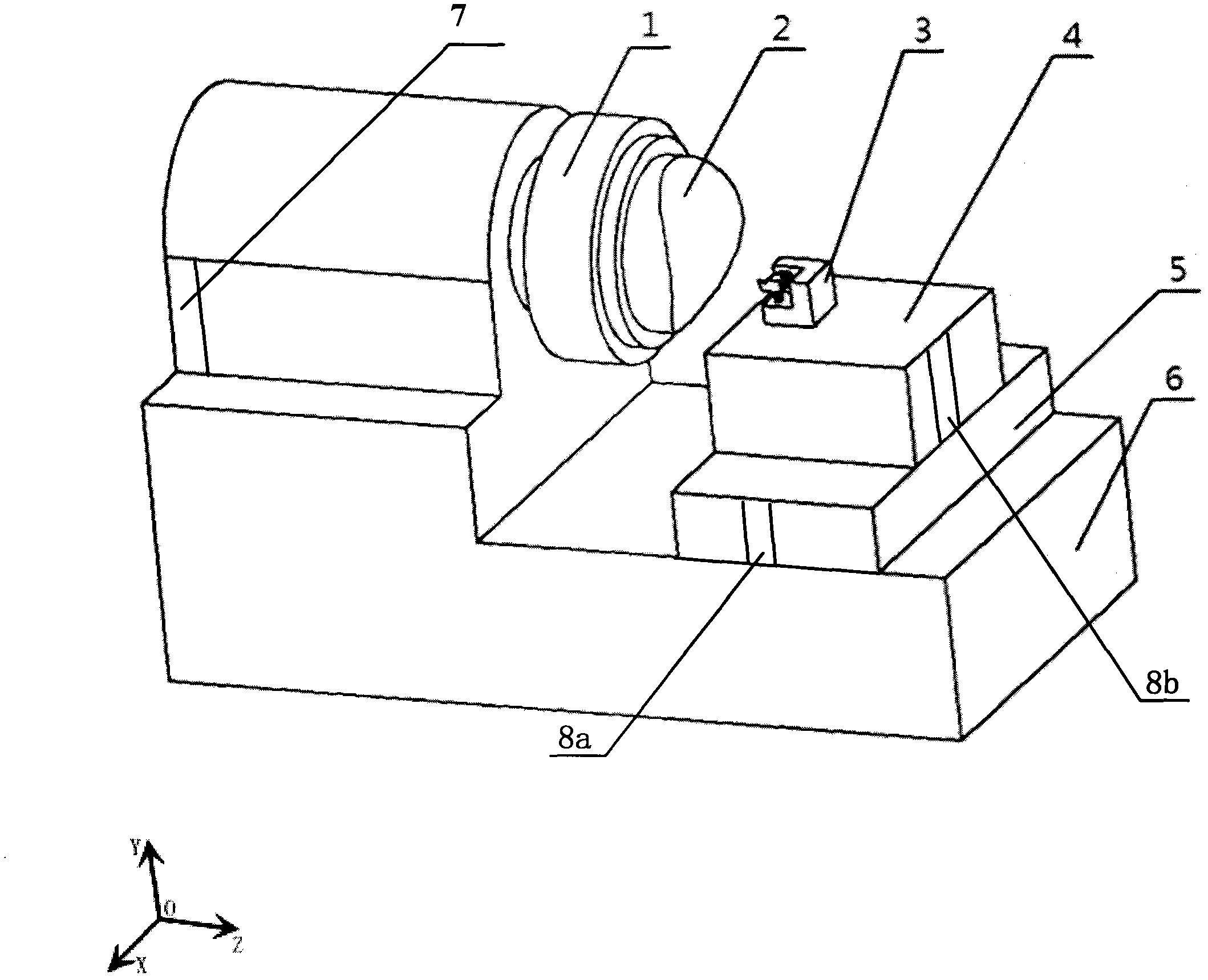
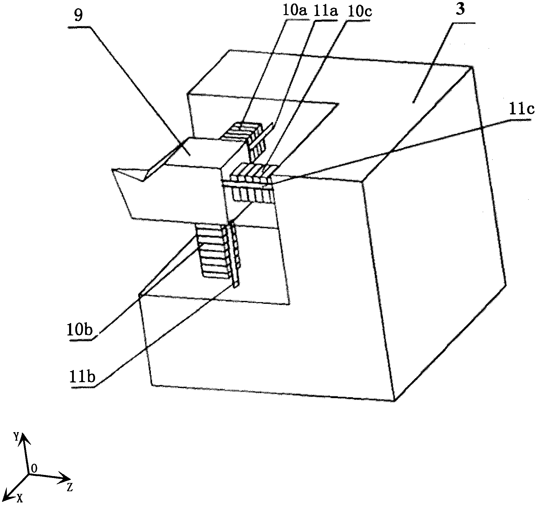
[0025] figure 1 with figure 2 The three-dimensional motion generating device 3 and its arrangement on an ultra-precision lathe are shown respectively. Such as figure 1 with figure 2 As shown, the three-dimensional motion generation device 3 is installed on the Z-axis slide plate 4 of the lathe, the Z-axis slide plate is installed on the X-axis slide plate 5 of the lathe, and the X-axis slide plate 5 is installed on the bed 6. The linear grating displacement sensor 8a is installed on the X-axis sliding plate 5, the X-direction linear grating displacement sensor 8b is installed on the Z-axis sliding plate 4, the spindle angle encoder 7 is installed on the bed, and the diamond tool 9 is respectively connected to the X-axis piezoelectric The stack 10a, the piezoelectric stack 10b in the Y-axis direction, and the piezoelectric stack 10c in the Z-axis direction are fixedly connected, the piezoelectric stack 10a in the X-axis direction, the piezoelectric stack 10b in the Y-axis ...
PUM
 Abstract
Description
Claims
Application Information