Discharging equipment for injection molding and processing technology

A technology of injection molding and injection molding equipment, which is applied in the field of unloading equipment and processing technology for injection molding, and can solve the problems of users' health impact, inconvenient use, and high surface temperature of products

Pending Publication Date: 2022-03-01
杭州煊赫电子有限公司
View PDF0 Cites 0 Cited by
  • Summary
  • Abstract
  • Description
  • Claims
  • Application Information

AI Technical Summary

Problems solved by technology

[0005] The purpose of the present invention is to provide a kind of unloading equipment and processing technology for injection molding to solve the problem that after the injection molding machine proposed in the above background technology is divided, the product will be stuck inside the fixed mold, and the mold cannot be demoulded smoothly, requiring the user to lean forward Go to the inside of the injection molding machine and pull out the product by hand, but the newly made product will emit toxic gas, and the surface temperature of the product is high, which will affect the health of the user and cause inconvenience in use

Method used


Image

  • Discharging equipment for injection molding and processing technology
  • Discharging equipment for injection molding and processing technology
  • Discharging equipment for injection molding and processing technology

Examples


Embodiment 1

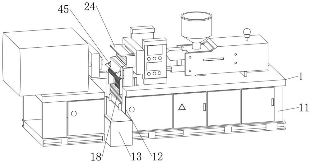
[0036] see Figure 1-8 , an embodiment provided by the present invention: a kind of unloading equipment for injection molding, comprising:

[0037] The cylinder used in this application is a product that can be purchased directly on the market, and its principle and connection mode are all prior art well known to those skilled in the art, so they will not be repeated here.

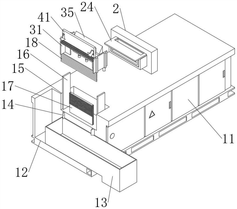
[0038] The injection molding equipment body 1, the injection molding equipment body 1 includes a body 11, the top surface of the body 11 is provided with a storage tank 12, the inside of the storage tank 12 is slidably installed with a water tank 13, and the inner wall of the storage tank 12 is fixedly installed. A movable groove 15 is provided on the side wall of 12, a guide plate 16 is fixedly installed on the inner wall of the movable groove 15, and a rack plate 17 and a blind 18 are fixedly installed on the bottom wall of the movable groove 15;

[0039] Stripping structure 2, stripping structure 2 com...

Embodiment 2

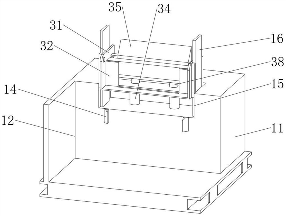
[0049] On the basis of Embodiment 1, after parting the mold, start the first cylinder 34, the first cylinder 34 will lift the cover 31 upwards, which can drive the cover 31 to move upwards on the outside of the rack plate 17, and the cover 31 will drive the gear cylinder 41 and The rack plate 17 is engaged, and the material guide plate 42 rotates around the gear cylinder 41, so that the gear cylinder 41 tends to be vertical, and after the first cylinder 34 is lifted, the material guide plate 42 is located on the left side of the product 28, and then the second cylinder is started. Two cylinders 38, the second cylinder 38 lifts the inserting plate 35 upwards, the top of the inserting plate 35 is inserted into the movable cavity 23, contacts with the top plate 26, and pushes the top plate 26, and the top plate 26 drives the push plate 25 to move inside the mold cavity 22 , the product 28 inside the mold cavity 22 can be ejected to the left, the product 28 is in contact with the f...

Embodiment 3

[0052] The present invention also provides a kind of unloading process for injection molding, the specific steps are as follows:

[0053] S1: Start the first cylinder 34, the first cylinder 34 lifts the outer cover 31 upwards, the outer cover 31 drives the gear cylinder 41 to mesh with the rack plate 17, the material guide plate 42 rotates around the gear cylinder 41, and rises with the outer cover 31 to guide the material The plate 42 is kept parallel to the mold 21 and is located on the right left side of the product 28;

[0054] S2: start the second cylinder 38, the second cylinder 38 lifts the inserting plate 35 upwards, inserting the inserting plate 35 upwards into the inside of the movable chamber 23, pushes the top plate 26, the top plate 26 drives the push plate 25 to move to the left, and pushes the push plate 25 The product 28 is pushed out from the mold cavity 22, and the product 28 is stuck between two sets of fixed claws 44;

[0055] S3: The second cylinder 38 re...


PUM


Abstract

The invention relates to the technical field of injection molding unloading, in particular to unloading equipment for injection molding, which comprises an injection molding equipment body, the injection molding equipment body comprises a machine body, a storage groove is formed in the top surface of the machine body, a water tank is slidably mounted in the storage groove, and an abutting plate is fixedly mounted on the inner wall of the storage groove; a containing groove is formed in the top face of the machine body, a movable groove is formed in the side wall of the containing groove, a guide plate is fixedly installed on the inner wall of the movable groove, a rack plate and a blind are fixedly installed on the bottom wall of the movable groove, the stripping structure comprises a mold, the mold is fixedly installed on the top face of the machine body, and a mold groove is formed in the side wall of the mold. According to the discharging equipment, after an injection molding machine is subjected to mold splitting, a product can be ejected out of a mold, so that automatic discharging of the product is achieved, the product can be fixed, the product is lowered to a low position, the product can slide into a water tank conveniently, and the product can be cooled.

Description

technical field [0001] The invention relates to the technical field of injection molding unloading, in particular to an injection molding unloading device and a processing technology. Background technique [0002] Injection molding is a method of producing shapes for industrial products, and products usually use rubber injection molding and plastic injection molding. Injection molding machine (referred to as injection machine or injection molding machine) is the main molding equipment for making thermoplastic or thermosetting materials into various shapes of plastic products using plastic molding molds. Injection molding is realized through injection molding machines and molds. [0003] However, after the injection molding machine splits the mold, the product will be stuck inside the fixed mold and cannot be demoulded smoothly. The user needs to lean inside the injection molding machine and pull the product out by hand, but the newly made product will emit toxic gas, and Th...

Claims


Application Information

Patent Timeline
Patent Type & Authority Applications(China)
IPC IPC(8): B29C45/17B29C45/40B29C45/42B29C45/72
CPCB29C45/1769B29C45/4005B29C45/4225B29C45/7207B29C2045/177Y02W30/62
Inventor 刘剑锋
Owner 杭州煊赫电子有限公司
Why Eureka
Try Eureka