Double-duct hybrid power device, hovercar and control method

A hybrid and ducted technology, applied in flight direction control, aircraft control, aircraft, etc., can solve the problems of not obvious advantages in transportation efficiency, insufficient battery energy density, and high cost

Active Publication Date: 2022-03-01
BEIJING NEW ENERGY VEHICLE TECH INNOVATION CENT CO LTD
View PDF7 Cites 2 Cited by
  • Summary
  • Abstract
  • Description
  • Claims
  • Application Information

AI Technical Summary

Problems solved by technology

On the ground, all kinds of electric vehicles will be popularized one after another, but in the aspect of air vehicles, the progress of electrification is relatively slow, which is mainly caused by two reasons: (1) The energy density of the battery is not high enough to achieve a certain battery life The volume and weight of the battery required for the mileage are too large, not only that, but the installation of so many batteries also makes the cost high and cannot be accepted by ordinary consumers; (2) the thrust produced by the current electric fan technology is too small, and the battery After the heavy weight, the thrust-to-weight ratio is seriously insufficient, the flight performance is poor, and the transportation efficiency advantage of air traffic over ground traffic is not obvious

Method used


Image

  • Double-duct hybrid power device, hovercar and control method

Examples


Embodiment 1

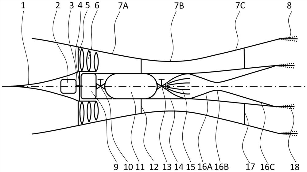
[0046] A double-duct hybrid power device for supersonic flight, including an outer jet driving part composed of an electric fan, an outer duct and an outer vector nozzle, and an inner jet composed of a high-pressure air tank 11, an inner duct and an inner vector nozzle drive part.

[0047] The center of the front end of the power unit has a pointed cone-shaped front center body 1 suitable for supersonic airflow, while the outer edge of the intake end has a guide lip, and the design of the well-known intake end (such as the intake end) is adopted inside the intake end. bulge and air intake lip), and a guide vane 5 is arranged downstream of the intake end, and the downstream of the guide vane 5 is a fan blade 6, and the fan blade 6 is installed on the fan hub 4, and the fan In the center of the hub 4 there is a drive shaft 3 which is actually the output shaft of the motor 2 installed downstream of the front central body 1 . The downstream of the fan blade 6 is provided with an ...

Embodiment 2

[0062] A flying car includes a storage battery and the double-duct hybrid power device for supersonic flight described in Embodiment 1.

[0063] The battery supplies power to the electric fan and the compression propulsion system, and the electric fan charges the battery when it is reversed.

Embodiment 3

[0065]A control method for a flying car in Embodiment 2, including

[0066] Judging the running status, if it is driving on the ground or flying below the preset altitude, it will be driven by electric fans; if it is flying above the preset altitude, it will be driven by compressed air;

[0067] During operation, it is judged whether the thrust provided by the current electric fan meets the requirements. If so, the electric fan is used for propulsion. If not or the battery power is lower than the threshold, the compression propulsion system releases compressed air to provide thrust.


PUM


Abstract

The invention relates to the technical field of vehicles, in particular to a double-duct hybrid power device, a hovercar and a control method.The device comprises an outer duct, an inner duct and a compression propulsion system using compressed air as a working medium, the inner duct is arranged in the outer duct, and the outer duct and the inner duct are coaxially arranged; the outer duct comprises an air inlet end and an air outlet end, and an electric fan is arranged in the outer duct at the air inlet end; according to the description, the endurance mileage can be increased by using the compressed air, so that the unmanned aerial vehicle can achieve supersonic flight at a lower flight height; the air compressor and the outside atmosphere are used for supplementing pressure for the high-pressure air tank, the thrust ratio of the inner duct and the outer duct can be flexibly adjusted, and the hovercar can have higher thrust performance at the cost of sacrificing a certain mileage.

Description

technical field [0001] The invention relates to the technical field of vehicles, in particular to a double-duct hybrid power device, a flying car and a control method. Background technique [0002] With the continuous development of new energy technologies, the electrification of vehicles is imperative. On the ground, all kinds of electric vehicles will be popularized one after another, but in the aspect of air vehicles, the progress of electrification is relatively slow, which is mainly caused by two reasons: (1) The energy density of the battery is not high enough to achieve a certain battery life The volume and weight of the battery required for the mileage are too large, not only that, but the installation of so many batteries also makes the cost high and cannot be accepted by ordinary consumers; (2) the thrust produced by the current electric fan technology is too small, and the battery After the heavy weight, the thrust-to-weight ratio is seriously insufficient, the f...

Claims


Application Information

Patent Timeline
Patent Type & Authority Applications(China)
IPC IPC(8): B60F5/02B64C15/02B64D27/24B64C30/00
CPCB60F5/02B64C15/02B64D27/24B64C30/00B64U50/19B64U50/14Y02T50/60
Inventor 袁一卿
Owner BEIJING NEW ENERGY VEHICLE TECH INNOVATION CENT CO LTD
Why Eureka
Try Eureka