Floating roof oil storage tank

An oil storage tank and floating roof technology, which is applied to tank cars, transportation passenger cars, railway car body parts, etc., can solve the problems of inability to foam filling, waste of equipment and funds for foam generators, and inability to cool the oil storage tank, reducing the number of settings. , the effect of reducing workload

Active Publication Date: 2022-03-01
蓝基工程科技有限公司
View PDF13 Cites 2 Cited by
  • Summary
  • Abstract
  • Description
  • Claims
  • Application Information

AI Technical Summary

Problems solved by technology

[0004] The purpose of the present invention is to solve the problem that the sprinkler system and the foam fire extinguishing system on the floating roof oil storage tank existing in the prior art are all fixed settings, resulting in the The spray system cannot fully cool down the oil storage tank, and the foam fire extinguishing system cannot quickly fill the foam to the connection between the floating roof and the tank wall, and setting more sprinklers and foam generators is a waste of equipment and funds , while increasing the workload of overhaul, and the proposed floating roof oil storage tank

Method used


Image

  • Floating roof oil storage tank
  • Floating roof oil storage tank
  • Floating roof oil storage tank

Examples


Embodiment 1

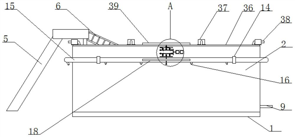
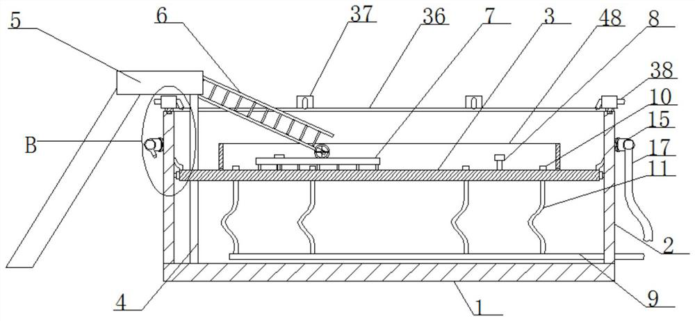
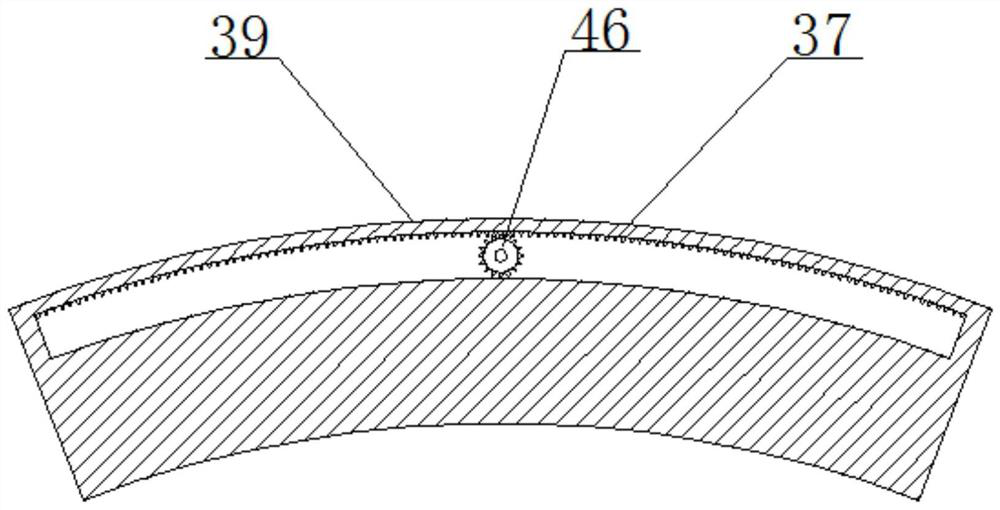
[0031] refer to Figure 1-8, a floating roof oil storage tank, comprising a tank bottom 1, an oil tank wall 2 and a floating roof 3, the oil tank wall 2 is fixedly arranged on the top of the tank bottom 1, the floating roof 3 is arranged in the oil tank wall 2, and the floating roof 3 The outer side of the floating roof 3 is provided with a ring sealing ring, the top of the floating roof 3 is provided with a tongue-shaped sealing ring, the floating roof 3 is provided with a sliding hole, and the sliding hole is provided with an oil dipping pipe 4, and the bottom end of the oil dipping pipe 4 is connected to the tank bottom 1. A ladder 5 is arranged on the outside of the top of the oil dipping pipe 4, and the ladder 5 is arranged on the outside of the oil tank wall 2. The ladder 5 is rotatably connected with a movable ladder 6, and the top of the floating roof 3 is fixedly connected with a track platform 7 by welding, and the movable ladder 6 The bottom end is slidably installe...

Embodiment 2

[0042] The difference from Embodiment 1 is that it includes a tank bottom 1, an oil tank wall 2 and a floating roof 3, and is characterized in that the oil tank wall 2 is fixedly arranged on the top of the tank bottom 1, and the floating roof 3 is arranged on the oil tank In the wall 2, a ring sealing ring is provided on the outside of the floating roof 3, a tongue-shaped sealing ring is provided on the top of the floating roof 3, a sliding hole is provided on the floating roof 3, and an oil dipping pipe 4 is arranged in the sliding hole, and the bottom of the oil dipping pipe 4 The end is connected to the bottom of the tank 1, and a ladder 5 is arranged on the outside of the top of the dipstick 4, and the ladder 5 is arranged on the outside of the tank wall 2. A movable ladder 6 is connected to the ladder 5 in rotation, and a track platform 7 is fixedly connected to the top of the floating roof 3. , the bottom end of the movable ladder 6 is slidingly installed on the track pla...


PUM


Abstract

The invention belongs to the field of floating-roof oil storage tanks, particularly relates to a floating-roof oil storage tank, and aims to solve the problems that a spraying system and a foam fire extinguishing system arranged on an existing floating-roof oil storage tank are fixedly arranged, so that the spraying system cannot comprehensively cool the oil storage tank, and the foam fire extinguishing system cannot quickly fill foams into a joint of a floating roof and an oil tank wall. In order to solve the problems that in the prior art, due to the fact that a large number of spraying heads and foam generators are arranged, equipment and funds are wasted, and meanwhile the overhaul work amount is increased, the following scheme is provided, the oil tank comprises a tank bottom, an oil tank wall and a floating roof, and a spraying system or a foam fire extinguishing system can be driven to swing by switching the rotation direction of a positive and negative rotation motor; the spraying system can comprehensively cool the oil storage tank, the foam fire extinguishing system can rapidly fill the joint of the floating roof and the oil tank wall with foam, the number of spray headers and foam generators can be reduced, and meanwhile the overhaul workload is reduced.

Description

technical field [0001] The invention relates to the technical field of floating roof oil storage tanks, in particular to a floating roof oil storage tank. Background technique [0002] Floating roof oil storage tank, referred to as floating roof tank, is an important category of oil storage tanks, mainly because it is designed with a "floating roof device" that can "float" on the oil surface and rise and fall with the oil level in the storage tank Different from ordinary fixed-roof oil tanks without this device, floating-roof oil storage tanks are divided into two types: inner floating roof type and outer floating roof type. Therefore, the evaporation loss of the stored materials can be greatly reduced. This kind of storage tank is widely used in the storage of light oil products such as gasoline, aviation kerosene, diesel oil and crude oil. Floating roof storage tanks are generally equipped with spray The shower system, in relatively hot weather, sprays water through the s...

Claims


Application Information

Patent Timeline
Patent Type & Authority Applications(China)
IPC IPC(8): B65D88/42B65D88/74B65D90/22A62C3/16A62C5/02
CPCB65D88/42B65D88/745B65D90/22A62C3/16A62C5/02B65D2590/0091
Inventor 黎文超戈峰
Owner 蓝基工程科技有限公司
Why Eureka
Try Eureka