Intelligent detection method for singular point characteristics of fluid conveying pipeline

An intelligent detection and pipeline technology, applied in pipeline systems, mechanical equipment, gas/liquid distribution and storage, etc., can solve the problems of many auxiliary structures, high cost, low singularity positioning accuracy, etc. The effect of suppressing the loss of conveying fluid and low cost of industrial application

Pending Publication Date: 2022-03-01
ZHENGZHOU UNIV
0 Cites 0 Cited by

AI-Extracted Technical Summary

Problems solved by technology

It is expected to change the current situation in the field of pipeline inspection, such as late detection, high cost...

Method used

After the point in time, the data collection contrast detection background parameters are based on machine learning to obtain pipeline singularity, perimeter characteristic change, this step is the key of intelligent detection of flow pipeline, adopt neural network based on deep machine learning from a large amount of data collected Obtain and strip the characteristic parameters of the singularity point and the characteristic parameters of the perimeter change, and compare and analyze them with the corresponding parameters in the background parameter set, so as to realize the characteristic analysis and high-precision positioning of the singularity point and perimeter of the pipeline, as shown in Figure 1;
Also comprise elastic base, described elastic base is annular spacer type and annular cuff type glue pad, array is provided with groove on described elastic base, vibration wave test m...

Abstract

The invention discloses an intelligent detection method for singular point features of a flow conveying pipeline, and the method comprises the following steps: firstly, forming a background parameter set; secondly, installing a vibration wave parameter test micro-nano device to each node position of the to-be-tested fluid conveying pipeline, and collecting pipeline global information transmitted between any two nodes on the to-be-tested fluid conveying pipeline through the vibration wave parameter test micro-nano device; and setting a pipeline singular point fracture threshold value. According to the method, the physical characteristic that water hammer vibration waves are transmitted along a pipeline line at the moment in the running process of a fluid conveying pipeline is utilized, vibration wave transmission parameters are tested at adjacent detection nodes, and on-chip integration is achieved through a vibration wave sensor and machine learning algorithm firmware; the flow conveying pipeline material change singular point, the pipe circumference contact boundary change and the like are obtained from the vibration wave transmission parameter set based on the modes of deep learning, data fusion and the like, and pre-judgment and fixed-point maintenance are actively achieved before the flow conveying pipeline singular point fracture threshold value is achieved. And constructing a novel intelligent detection method of the fluid conveying pipeline and optimizing fluid loss control.

Application Domain

Pipeline systems

Technology Topic

Feature (machine learning)Wave transmission +7

Image

  • Intelligent detection method for singular point characteristics of fluid conveying pipeline
  • Intelligent detection method for singular point characteristics of fluid conveying pipeline
  • Intelligent detection method for singular point characteristics of fluid conveying pipeline

Examples

  • Experimental program(1)

Example Embodiment

[0034] The following will clearly and completely describe the technical solutions in the embodiments of the present invention with reference to the accompanying drawings in the embodiments of the present invention. Obviously, the described embodiments are only some, not all, embodiments of the present invention. Based on the embodiments of the present invention, all other embodiments obtained by persons of ordinary skill in the art without making creative efforts belong to the protection scope of the present invention.
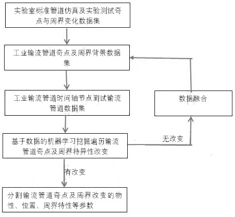
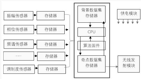
[0035] like figure 1 , 2 Shown in and 3, the present invention comprises the following steps:
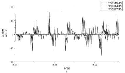
[0036] A: Collect data on the flow characteristics of standard pipelines by testing micro-nano devices through vibration wave parameters to form a background parameter set;
[0037] B: Install the vibration wave parameter test micro-nano device to each node position of the flow pipeline to be tested, and collect the pipeline global information transmitted between any two nodes on the flow pipeline to be tested through the vibration wave parameter test micro-nano device, the said The global pipeline information includes vibration amplitude, frequency, phase, modulation ratio, and frequency offset; these frequency domain information can be related to the physical properties of the pipeline based on specific expressions, such as f=(k/m)1/2.
[0038] C: Set the sampling time length of the vibration wave parameter data and the start time point, and write all the singular points and perimeter characteristics of the flow transmission pipeline collected before the time point into the pipeline detection background parameter set, so as to realize the integration of all background parameter sets in the early stage Fusion, and as the next detection background parameter set; singularity characteristics include singularity position, singularity geometry, singularity spatial distribution, singularity physical characteristics. Perimeter characteristics include: contact stress around the tube, contact material around the tube, and supporting devices around the tube.
[0039] D: Compare and detect the background parameter set with the data set collected after the set time point, and the two data sets are based on deep machine learning to obtain pipeline singularity and perimeter characteristic changes. For example, new spectral components are generated, the spectral range is narrowed, and the amplitude is increased or decreased.
[0040] E: Set the pipe singularity rupture threshold based on a large number of experimental and theoretical analysis results. The lowest value of the pressure flow), below the pipeline rupture threshold (95%), that is, the singularity characteristic forms a wireless signal and transmits it to the regional control center;
[0041] F: After the information obtained by the node is processed and filtered (the singularity position and physical properties of the singularity are obtained from the spectrum distribution, spectrum range, amplitude change, and frequency modulation coefficient calculation of the spectrum data set), the adaptive construction network based on the node ID will transfer the pipeline information Transmission, concentrated in the master control center.
[0042] The said node positions include array manholes, switch stations, pressure regulating stations, valves and other control devices to ensure the operation of the flow transmission pipeline.
[0043] The vibration wave parameter test micro-nano device includes a sensing array composed of sensing micro-nano devices, a control IC, a memory, and a data transmission unit, and the output end of the sensing micro-nano device array is connected to the input end of the control IC , the output end of the control IC is connected to the master control center through the data transmission unit.
[0044] The sensing micro-nano device includes an amplitude sensor, a phase sensor, a spectrum sensor, and a modulation sensor. In subsequent experimental research, other sensors can also be set according to actual needs.
[0045] The detection node device includes firmware integrating deep learning, data fusion and other algorithms, as well as micro-nano sensor arrays for collecting vibration wave parameter sets, control system system hardware, and signal transmission system hardware;
[0046] It also includes an elastic base, the elastic base is an annular gasket type and an annular sleeve type rubber pad, the elastic base is arrayed with grooves, and the vibration wave test micro-nano devices are embedded in the grooves Inside; the characteristic size of the vibration wave test micro-nano device matches the national standard pipe connector. The micro-nano node device is embedded in the elastic substrate, and the geometric size of the relevant detection unit is constructed according to the national standard pipeline characteristic size; it is convenient for a stable fit with the node, and does not cause additional structural changes to the node.
[0047] Its test data set is input into the machine learning network, and the data is processed in real time and on the spot to form the background parameter set of the pipeline between two nodes and the singular point characteristic parameter set; the data processing firmware, control IC, storage unit, and data transmission unit are integrated in the detection Unit device; The vibration wave transmission background parameter set of the newly-built initial flow pipeline is derived from the fusion experiment results of the simulation results of the characteristics of the flow pipeline in the standard laboratory and the environmental detection; based on the time axis segmentation, the data obtained before the segmentation point and the initial data set Data fusion is formed to form a new characteristic parameter background of the flow pipeline; the background parameter set of the vibration wave transmission of the flow pipeline, wherein the data obtained after the time division point is compared with the background parameter set, and when there is no specific change, the data continues to be fused to form A new background parameter set of the flow pipeline; the background parameter set of the flow pipeline, wherein the data obtained after the time division point is compared with the background parameter set, and when there is a specific change, the background parameter set and the new test vibration wave are transmitted based on the vibration wave The differential calculation of the parameter set obtains the characteristics of the singular point and the circumference of the pipeline; the characteristics of the singularity of the pipeline and the characteristics of the circumference of the pipeline form a transmission data packet, which is transmitted to the master control center based on the adaptive network of the node ID;
[0048] Set the singularity threshold based on the physical properties of the pipeline material and the surrounding environment characteristics experimental results and simulation results. When the test data value reaches 95% of the threshold, an alarm signal is sent to notify the cut-off maintenance;
[0049] The singular point characteristics of the flow pipeline include the shape, depth, and distribution of cracks on the pipe wall; the thickness, distribution, and shape of the corrosion-thinned area; Distribution shape, stress bearing size. Changes in the perimeter of the flow pipeline include changes in the contact medium (soil, cement, water, air, metal), changes in the magnitude of the contact stress, changes in the rigidity of the fixture support, and changes in the amplitude of environmental vibrations.
[0050] specific as image 3 The change of the Young's modulus of the surface conveying pipe will lead to the change of the vibration wave amplitude, and the amplitude of the wave parameter is related to the Young's modulus of the conveying pipe. During the operating conditions of the flow pipeline, the Young's modulus of the pipe wall at the singularity position changes due to corrosion, cracks, and thickening, which can be tested from the characteristics of the vibration wave amplitude.
[0051] Figure 4 It is the change of the vibration wave parameters caused by the flow velocity of the fluid in the flow pipeline, which shows that there is a relationship between the vibration wave amplitude and the change of the fluid flow velocity. Due to the accumulation of impurities in the pipeline, the diameter of the pipe changes and then affects the flow rate of the flow. The change of the amplitude of the vibration wave obtained from the test node can form a test.
[0052] Figure 5 It is the change of the Young's modulus of the contact material around the flow pipeline that leads to the change of the amplitude of the vibration wave. The contact materials in the working conditions around the flow pipe are generally soil, cement, metal (ship), water and air. Judging from the influence of the contact interface of soil (water content, sand content) with different Young's modulus on the vibration wave amplitude, the impact is obvious. Correspondingly, the impact of cement and metal materials with higher Young's modulus on the vibration wave transmission must be more obvious, and the impact of water and air with lower Young's modulus must also exist. From the change of different physical materials, such as changing from soil to water or air, from metal to water or air, the vibration wave parameter test can test and distinguish this change.
[0053] Image 6 It is the influence of the Poisson's ratio of the flow pipeline material on the amplitude of the vibration wave. The results show that the material at the singular point of the flow pipeline is modified, and the Poisson's ratio changes, which can be reflected in the change of the vibration wave amplitude.
[0054] Figure 7 It is the cracks at different positions and different depths on the flow pipeline. Although they have not yet caused fluid leakage, they also have an impact on the amplitude of the vibration wave. By testing the amplitude variation of the vibration wave, it is also possible to detect part of the crack-like singularity information on the flow pipeline.
[0055] from Figure 3-Figure 7 It can be confirmed that the singular point characteristics of the flow pipeline are related to the vibration wave amplitude. Therefore, the multi-parameter, multi-data based big data mining method can obtain the singularity characteristics of the flow pipeline from the change of wave parameters.
[0056] When the present invention is actually used, firstly, the vibration wave test micro-nano device array is installed at the node positions of the flow pipeline inspection well and the switch station, and the detection node monitors in real time and detects the water hammer vibration signal transmitted from both sides of the node;
[0057] Then test the micro-nano array to obtain the whole domain information of the vibration wave transmitted between the two nodes, such as amplitude, frequency, phase, modulation ratio, frequency offset, etc., such as figure 2 As shown, the sensor array collects a variety of information transmitted by the water hammer vibration wave, which is stored and processed by the processing center through the deep machine learning algorithm and data fusion algorithm to obtain the background information of the flow pipeline between the two nodes and the singularity, circumference Evolutionary information such as world change specificity;
[0058] The re-detection node integrates algorithm firmware such as deep learning and data fusion, and forms an on-chip system with the detection node detection micro-nano device array, control IC, storage, and data transmission unit; the data set divided by calculation processing is transmitted by the wireless transmission unit;
[0059] The system-on-chip is embedded in the elastic substrate, and the geometric dimensions of the detection nodes are constructed according to the national standard pipeline characteristic dimensions. Construct the detection nodes, which are gasket type and sleeve type respectively. The use of elastic base is mainly to facilitate the installation of various flow pipeline nodes and reduce the cost of laying test nodes;
[0060] The characteristic data of the flow pipeline obtained through laboratory simulation and experiment are used as the background parameter set of pipeline physical properties before the detection time point of the new pipeline singularity. In view of the fact that there is no background parameter set source for the first use of the pipeline network, the standard laboratory's flow pipeline test, simulated physical properties, and perimeter characteristics are used as the initial background;
[0061] Set the length of the interval time, and write the singular point and perimeter characteristics of the flow pipeline collected before this time point into the pipeline detection background parameter set to realize the fusion of all background parameter sets in the early stage. The data processing flow is as follows: figure 1 shown;
[0062] After the time point, the data collected and compared with the detection background parameters are based on machine learning to obtain the singularity of the pipeline and the change of the perimeter characteristics. This step is the key to the intelligent detection of the pipeline. The neural network is used to obtain, Strip the characteristic parameters of the singularity and the characteristic parameters of the perimeter change, and compare and analyze with the corresponding parameters in the background parameter set to realize the characteristic analysis and high-precision positioning of the singularity and the perimeter of the pipeline, such as figure 1 shown;
[0063]The pipeline singularity threshold is set based on the basis of experiments and theoretical analysis. Below the pipeline rupture threshold, parameters such as the singularity position and physical properties of the singularity are collected in the control center, and the flow is cut off for maintenance. Different materials, different topological structures, different contact interfaces and surrounding environment parameters have different thresholds for rupture singularity of the flow pipeline. Through a large number of experiments and simulation analysis, the stress bearing strength, corrosion rate, stress concentration, etc. of the specific environment and specific material flow pipelines are set as the corresponding thresholds. The system analyzes and judges according to the test results. When it reaches 95% of the threshold, it means There is a risk of rupture at the point of singularity, which requires cut-off maintenance;
[0064] After processing and filtering the information obtained by the nodes, a network is adaptively established based on the node ID to transmit the pipeline information, and the nodes automatically communicate with surrounding nodes, and the data sets carry ID information, such as Image 6 shown. The data is centralized in the master control center. In order to achieve centralized control, the singular point mutation information of the inter-node flow transmission pipeline obtained by the nodes is relayed and transmitted by each node, and finally returned to the master control center for processing. An intelligent processing chain is formed to reduce the cost of pipeline testing.
[0065] Singularity can be regarded as an abnormal state area that occurs during the use of the pipeline, including crack shape; crack spatial distribution; crack geometric size; corrosion and thinning area of ​​the pipeline wall during long-term use of the pipeline; changes in the supporting environment around the pipeline Or the area of ​​uneven stress applied to the pipe wall caused by water hammer vibration; the conversion joint between straight pipe and curved pipe and straight pipe; fluid impurities gradually accumulate at the high friction point of the pipe wall to block the pipe diameter reduction area, etc. The definition of singularity can technically clarify the potential risk points of the pipeline, which has more engineering value than detecting/monitoring the actual leakage point of the pipeline, such as realizing pre-leakage monitoring, active detection, intelligent positioning, and real-time monitoring.
[0066] In the description of the present invention, it should be noted that for orientation words, such as the term "center", "horizontal", "longitudinal", "length", "width", "thickness", "upper", "lower" , "Front", "Back", "Left", "Right", "Vertical", "Horizontal", "Top", "Bottom", "Inner", "Outer", "Clockwise", "Counterclockwise" The indicated orientation and positional relationship are based on the orientation or positional relationship shown in the drawings, which are only for the convenience of describing the present invention and simplifying the description, rather than indicating or implying that the referred device or element must have a specific orientation or be constructed in a specific orientation. and operation, should not be construed as limiting the specific protection scope of the present invention.
[0067] It should be noted that the terms "first" and "second" in the specification and claims of the present application are used to distinguish similar objects, but not necessarily used to describe a specific order or sequence. It should be understood that the data so used may be interchanged under appropriate circumstances for the embodiments of the application described herein. Furthermore, the terms "comprising" and "having", as well as any variations thereof, are intended to cover a non-exclusive inclusion, for example, a process, method, system, product or device comprising a series of steps or elements is not necessarily limited to the expressly listed instead, may include other steps or elements not explicitly listed or inherent to the process, method, product or apparatus.
[0068] Note that the above are only preferred embodiments and application technical principles of the present invention. Those skilled in the art will understand that the present invention is not limited to the specific embodiments described herein, and that various obvious changes, readjustments and substitutions can be made by those skilled in the art without departing from the protection scope of the present invention. Therefore, although the present invention has been described in detail through the above embodiments, the present invention is not limited to the specific embodiments described here, and can also include more other effective embodiments without departing from the concept of the present invention. The scope of the present invention is determined by the appended claims.

PUM

no PUM

Description & Claims & Application Information

We can also present the details of the Description, Claims and Application information to help users get a comprehensive understanding of the technical details of the patent, such as background art, summary of invention, brief description of drawings, description of embodiments, and other original content. On the other hand, users can also determine the specific scope of protection of the technology through the list of claims; as well as understand the changes in the life cycle of the technology with the presentation of the patent timeline. Login to view more.

Similar technology patents

Monitoring method and system of intelligent power distribution cabinet

PendingCN114825623AImprove monitoring effectimprove accuracy
Owner:深圳市茂和机电有限公司

Power system main and auxiliary equipment event monitoring modeling method

PendingCN113962051Areduce work stressImprove monitoring effect
Owner:BEIJING KEDONG ELECTRIC POWER CONTROL SYST +1

Real-time surveying and mapping device and method based on foundation pit deformation monitoring

ActiveCN113668621AImprove monitoring effectIncrease the scope of application
Owner:山东志诚地理信息技术有限公司

Vehicle-mounted protecting monitoring method

InactiveCN107554449AImprove monitoring effect
Owner:成都华科威电子科技有限公司

Monitoring device for computer room of internet of things

PendingCN114811352AExpand the scope of monitoringImprove monitoring effect
Owner:柳州工学院

Classification and recommendation of technical efficacy words

  • Improve monitoring effect

Flow monitoring method, device and system

ActiveCN103997439AImprove monitoring effect
Owner:TENCENT TECH (SHENZHEN) CO LTD +1

UAV (unmanned aerial vehicle)-based pollution monitoring method and system

ActiveCN109406716AImprove monitoring effect
Owner:HAOXIANG ELECTRIC ENERGY KUNSHAN

Digging and anchoring all-in-one machine monitoring system based on digital twinning technology

ActiveCN113221461AImprove monitoring effect
Owner:TAIYUAN UNIV OF TECH

Index data processing method and device, equipment and storage medium

PendingCN113010805AImprove efficiencyImprove monitoring effect
Owner:TENCENT TECH (SHENZHEN) CO LTD

Forest fire multi-defense-line real-time monitoring system based on distributed optical fiber sensing technology

ActiveCN114093112AImprove monitoring effectimprove security
Owner:南京光蓝物联网科技有限公司
Why Eureka
Try Eureka