
Oil supply atomization device, combustion chamber device and micro jet engine

A technology of atomization device and combustion chamber, which is applied in combustion chamber, engine element, continuous combustion chamber, etc., can solve the problems affecting the reliability and stability of micro jet engine, insufficient fuel evaporation process, and poor fuel atomization degree, etc. The problem is that it is not easy to surge and stop in the air, the temperature field is also distributed evenly, and it is not easy to stall.

Pending Publication Date: 2022-03-01
付柏山
View PDF0 Cites 1 Cited by
  • Summary
  • Abstract
  • Description
  • Claims
  • Application Information

AI Technical Summary

Problems solved by technology

[0004] However, the fuel in the hook-type stainless steel evaporating tube only relies on the short evaporating tube for heat transfer, which makes the evaporation process of the fuel insufficient, resulting in poor atomization of the fuel, resulting in unstable combustion and excessive temperature at individual points. , which will directly affect the normal working conditions and the reliability and stability of the tiny jet engine, and even cause surge and parking in severe cases

Method used


Image

  • Oil supply atomization device, combustion chamber device and micro jet engine
  • Oil supply atomization device, combustion chamber device and micro jet engine
  • Oil supply atomization device, combustion chamber device and micro jet engine

Examples


Embodiment Construction

[0039] The following will clearly and completely describe the technical solutions in the embodiments of the present invention with reference to the accompanying drawings in the embodiments of the present invention. Obviously, the described embodiments are only some, not all, embodiments of the present invention. Based on the embodiments of the present invention, all other embodiments obtained by persons of ordinary skill in the art without making creative efforts belong to the protection scope of the present invention.

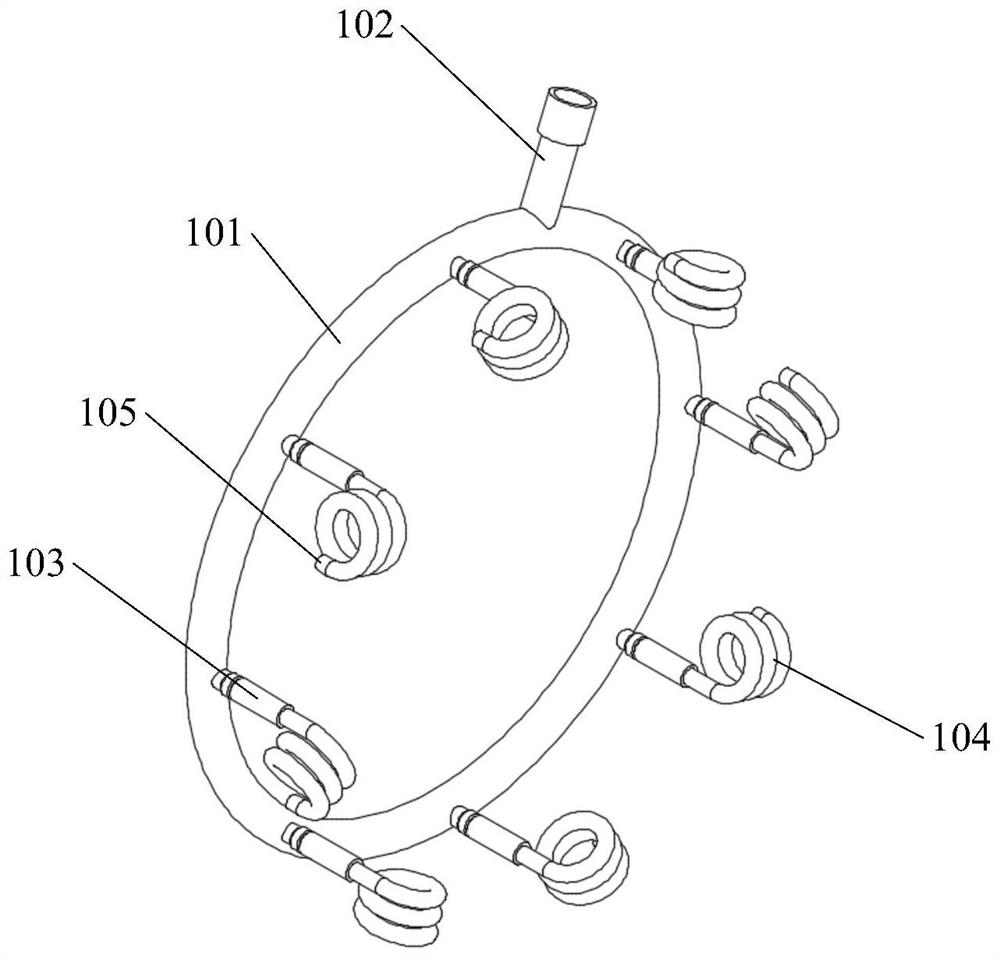
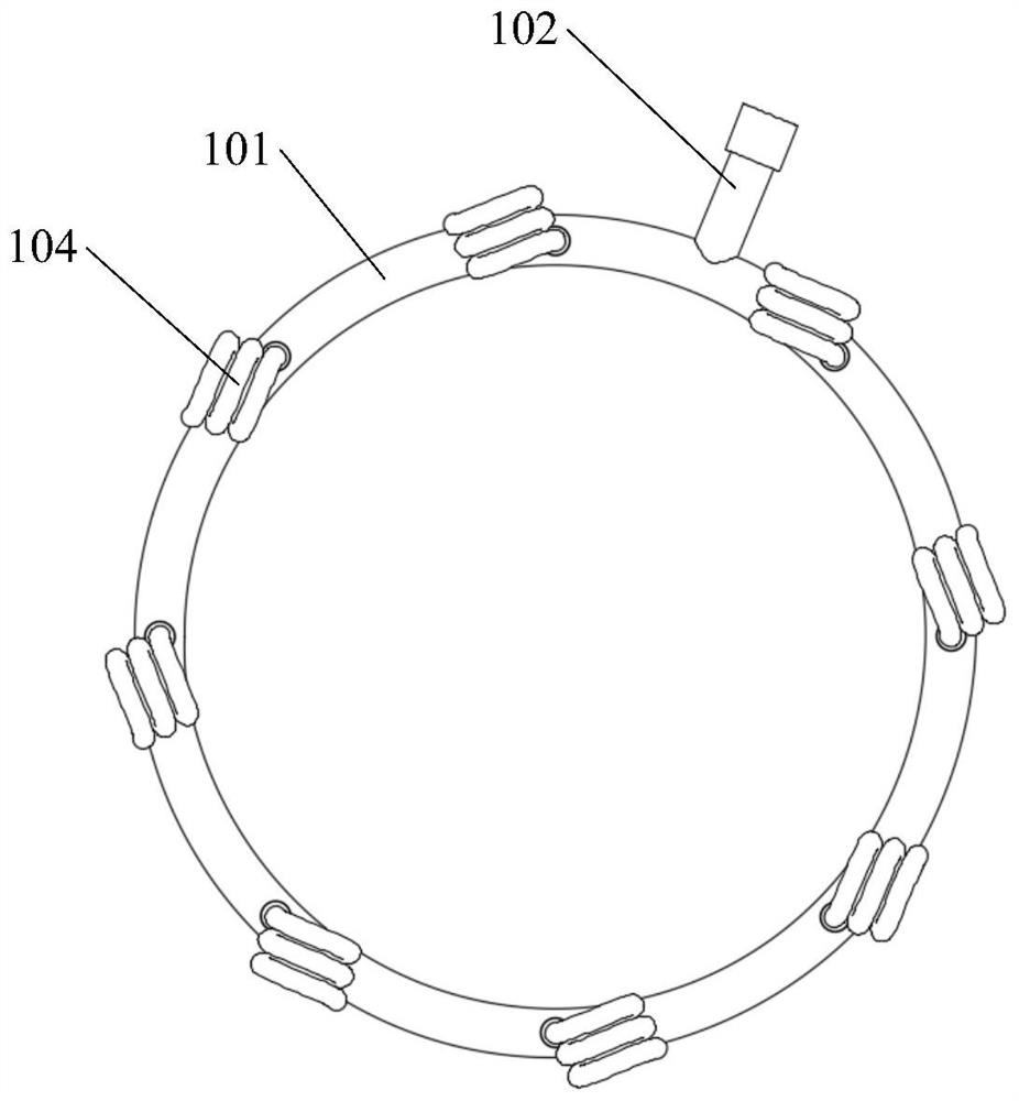
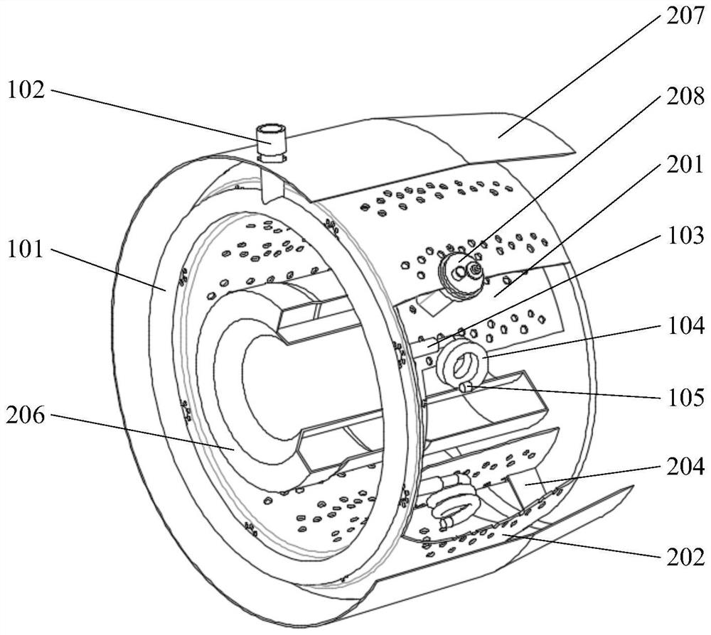
[0040] The core of the present invention is to provide an oil supply atomizing device, which can fully vaporize the fuel before entering the combustion chamber 201, so that the atomization degree of the fuel is high. Another core of the present invention is to provide a combustion chamber device including the above-mentioned oil supply atomization device, which has stable combustion and uniform temperature field in the combustion chamber 201 . Another core of ...


PUM


Abstract

The invention discloses an oil supply atomization device, a combustion chamber device and a micro jet engine, and the oil supply atomization device comprises an oil supply ring connected with an oil supply header pipe; and the evaporation pipe comprises a preheating part and an evaporation part, one end of the preheating part is connected with the oil supply ring, the other end of the preheating part is connected with the evaporation part, and the periphery of the preheating part is wrapped with a heat conduction piece. During working, the oil supply main pipe supplies fuel to the oil supply ring, the fuel enters the evaporation pipe from the oil supply ring and firstly enters the preheating part, and the heat conduction piece can quickly transfer heat in the combustion chamber to the fuel entering the preheating part, so that the fuel enters the evaporation part after being quickly preheated and is sprayed out after further heat transfer by the evaporation part; according to the micro jet engine, fuel can be fully preheated before entering the combustion chamber, so that the fuel is fully evaporated, atomized fuel hot steam which is uniformly distributed is formed, the atomization degree of the fuel is high, combustion is more sufficient and stable, the combustion chamber is not prone to stall, and the micro jet engine is not prone to surging, stopping in the air and the like.

Description

technical field [0001] The invention relates to the technical field of miniature jet engine components, and more specifically, relates to an oil supply atomizing device. In addition, the present invention also relates to a combustion chamber device comprising the above-mentioned fuel supply atomizing device and a microjet engine comprising the combustion chamber device. Background technique [0002] In high-speed small aircraft such as high-speed drones, cruise missiles, jet model aircraft, and target drones, and micro gas turbine power plants, the combustion chamber is a key component, and the performance of the combustion chamber directly affects the performance and reliability of the engine. [0003] In the prior art, in order to simplify the structure and reduce the size and weight of the combustion chamber, the oil supply atomization device of the combustion chamber adopts a hook-type stainless steel evaporator tube, that is, the fuel is atomized by the hook-type stainl...

Claims


Application Information

Patent Timeline
IPC IPC(8): F23R3/32F02C7/224
CPCF23R3/32F02C7/224F05D2240/36
Inventor 付柏山
Owner 付柏山
Learn More