A forward and reverse centrifugal turbine engine

A turbine engine and centrifugal technology, applied in the direction of machines/engines, gas turbine devices, mechanical equipment, etc., can solve the problems of low technical requirements, difficult multi-stage series connection, low efficiency, etc., and achieve small size, difficult surge, single The effect of high boost ratio

Active Publication Date: 2017-04-05
平邑现代中药产业园有限公司
View PDF5 Cites 0 Cited by
  • Summary
  • Abstract
  • Description
  • Claims
  • Application Information

AI Technical Summary

Problems solved by technology

The single-stage boosting ratio of the centrifugal compressor is high, and the one-stage centrifugal compressor can have the compression ratio of several stages of the axial flow compressor. The centrifugal jet engine has a simple structure, small size, low technical requirements, and is not easy to The advantage of surge occurs, but it is not easy to connect multiple stages in series to affect the total boost ratio of the system, and the efficiency is low. It is commonly used in the first stage of turboshaft engines and auxiliary power units of civil aviation airliners.

Method used


Image

  • A forward and reverse centrifugal turbine engine
  • A forward and reverse centrifugal turbine engine

Examples


Embodiment Construction

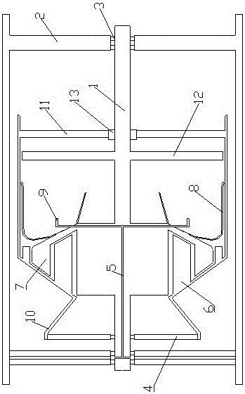
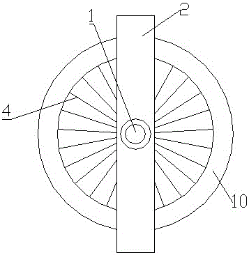
[0013] Such as figure 1 , 2 As shown, a forward and reverse centrifugal turbine engine includes an engine fixing frame 2, an inner rotor 1 is movably installed in the middle of the engine fixing frame 2, an oil supply pipe 5 is opened inside the inner rotor 1, and the inner rotor 1 is movable outside. The outer rotor 10 is installed, and one side of the outer rotor 10 is fixedly installed with the air inlet impeller 4, and the inner wall of the outer rotor 10 inside the air inlet impeller 4 is fixedly installed with the outer rotor compressor blade group 6, and the other side of the outer rotor 10 is fixedly installed with The outer rotor turbine 11 is fixedly installed on the inner rotor 1 on the side of the air inlet impeller 4 inside the outer rotor 10, and the inner rotor compressor blade group 7 matched with the outer rotor 10 is fixedly installed on the inner rotor 1 inside the outer rotor turbine 11. There is an inner rotor turbine 12, and a combustion chamber 8 is fix...


PUM


Abstract

The invention relates to a forward and reverse rotating centrifugal turbine engine. An inner rotor is movably installed in the middle of a fixing rack of the engine. An oil supply pipe is arranged in the inner rotor. An outer rotor is movably installed outside the inner rotor. A wind inlet impeller is fixedly installed at one side of the outer rotor. An outer rotor air compression blade set is fixedly installed on the inner wall of the outer motor of the inner side of the wind inlet impeller. An outer rotor turbine is fixedly installed at the other side of the outer rotor. An inner rotor air compression blade set matched with the wind inlet impeller is fixedly installed on the portion, located at one side of the wind inlet impeller in the outer rotor, of the inner rotor. An inner rotor turbine is fixedly installed on the portion, located at the inner side of the outer rotor turbine, of the inner rotor. A combustor is fixedly installed on the rear outer edge of the inner rotor air compression blade set and communicated with an oil spray pipe. The oil spray pipe is communicated with the oil supply pipe. Static blades are omitted, the engine is greatly simplified, the weight is reduced, and the engine has the advantages of being simple in structure, small in size, low in manufacturing technology requirement, and not prone to surging.

Description

technical field [0001] The invention relates to the mechanical field, in particular to an engine, in particular to a forward and reverse centrifugal turbine engine. Background technique [0002] Turbine engines with compressors are divided into two types: axial flow and centrifugal according to their compression methods. The compressors of axial flow engines have many blades, which are similar in shape to propeller blades, but are divided into "stator" and "rotor". two kinds. The rotor rotates like a propeller, pushing the airflow backwards during the rotation, at this time the pressure of the airflow will increase and the temperature will also increase. The function of the stator is to guide the airflow rotated by the rotor back to the axial direction, and enter the next set of rotors at the correct angle. Usually, a group of rotors and a group of stators are alternately configured, and a group of rotors and stators is called a first stage. Axial-flow compressors are lar...

Claims


Application Information

Patent Timeline
Patent Type & Authority Patents(China)
IPC IPC(8): F02C3/08
Inventor 常胜
Owner 平邑现代中药产业园有限公司
Why Eureka
Try Eureka