Continuous knotting test bench for multiple groups of knotters

A knotter and test bench technology, applied in the field of baling, can solve the problems of high failure rate, limited measurement parameters, inability to test multiple knotters, etc. Effect

Pending Publication Date: 2022-03-01
JIANGSU UNIV
View PDF0 Cites 0 Cited by
  • Summary
  • Abstract
  • Description
  • Claims
  • Application Information

AI Technical Summary

Problems solved by technology

Although domestic research on knotters started relatively late, a lot of new progress has been made. There is an urgent need to conduct related performance tests on improved knotters. However, the existing knotter test benches cannot test multiple knotters simultaneously testing, thereby prolonging the time spent on the testing process, with limited measurement parameters and a high failure rate, which does not meet the requirements for reliable continuous knot testing

Method used


Image

  • Continuous knotting test bench for multiple groups of knotters
  • Continuous knotting test bench for multiple groups of knotters
  • Continuous knotting test bench for multiple groups of knotters

Examples


Embodiment Construction

[0031] Embodiments of the present invention are described in detail below, examples of which are shown in the drawings, wherein the same or similar reference numerals designate the same or similar elements or elements having the same or similar functions throughout. The embodiments described below by referring to the figures are exemplary and are intended to explain the present invention and should not be construed as limiting the present invention.

[0032] In describing the present invention, it is to be understood that the terms "central", "longitudinal", "transverse", "length", "width", "thickness", "upper", "lower", "axial", The orientation or positional relationship indicated by "radial", "vertical", "horizontal", "inner", "outer", etc. is based on the orientation or positional relationship shown in the drawings, and is only for the convenience of describing the present invention and simplifying the description , rather than indicating or implying that the device or elem...


PUM


Abstract

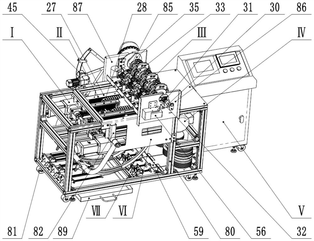
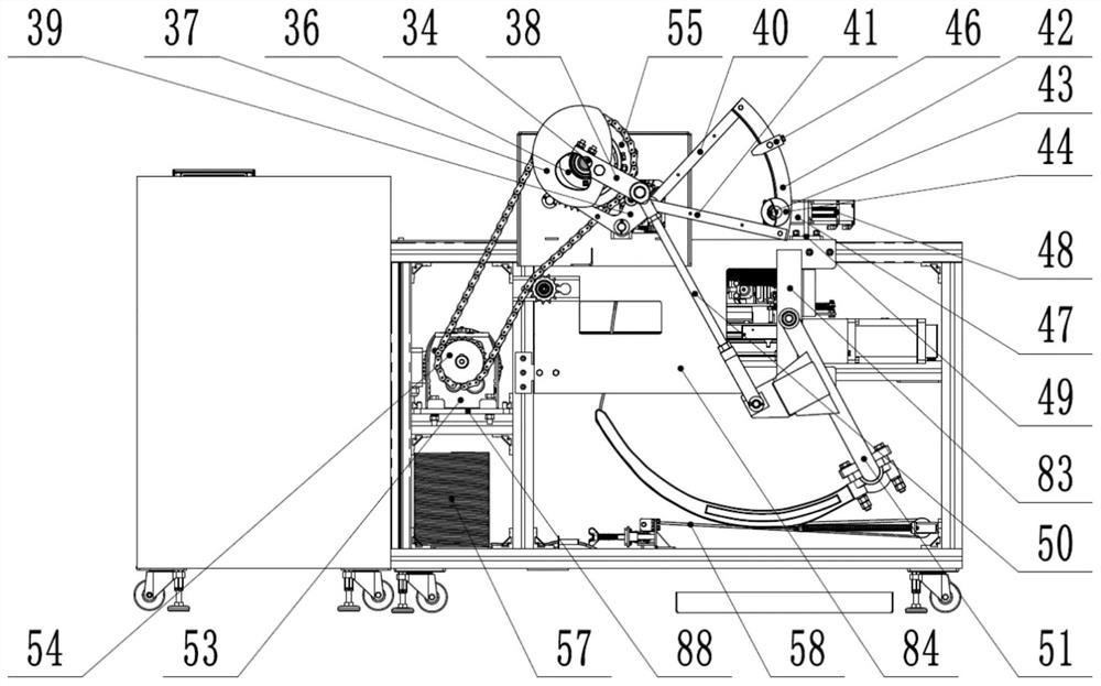
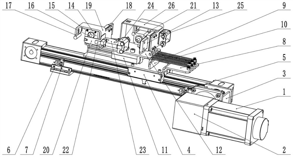
The invention provides a continuous knotting test bench for multiple groups of knotters. The continuous knotting test bench comprises a rope pulling system I, a rope releasing device II, a knotter main shaft transmission system III, a motor driving system IV, a control system V, a rack VI and a rope bundling pre-tightening force adjusting device VII, the bundling rope pre-tightening force adjusting device VII is used for clamping and tightening a bundling rope, the control system V controls the motor driving system IV to enable a rope needle of the knotter main shaft transmission system III to send the bundling rope to the knotter, and the rope pulling system I enables the bundling rope to form a to-be-knotted rope loop. A motor driving system IV drives a knotter main shaft transmission system III to enable the knotter to complete the knotting action, and a rope releasing device II brushes off a knotted rope ring from a rope pulling system I; the continuous knotting process of multiple groups of knotters under the condition of bale rebound can be simulated, the knotting speed can be controlled by adjusting the rotating speed of the motor driving system, simultaneous continuous knotting of the multiple groups of knotters is automatically realized, the time consumed in the testing process is shortened, the testing efficiency and the knot quality are improved, and the failure rate is reduced.

Description

technical field [0001] The invention belongs to the technical field of bundling, and in particular relates to a continuous knotting test bench for multiple groups of knotters. Background technique [0002] Nowadays, the square bale baler is widely used in agriculture. As an important part of the square bale baler, the performance of the knotter directly determines the working quality of the square bale baler. Although domestic research on knotters started relatively late, a lot of new progress has been made. There is an urgent need to conduct related performance tests on improved knotters. However, the existing knotter test benches cannot test multiple knotters simultaneously Testing, thus prolonging the time spent in the testing process, and its measurement parameters are limited, the failure rate is high, and it cannot meet the requirements for reliable continuous knot testing. Contents of the invention [0003] In view of the above technical problems, the present inven...

Claims


Application Information

Patent Timeline
Patent Type & Authority Applications(China)
IPC IPC(8): G01M99/00
CPCG01M99/008
Inventor 尹建军武鲁宁周脉乐王泽亮
Owner JIANGSU UNIV
Why Eureka
Try Eureka