Tool path generation method and device capable of automatically recognizing groove features and storage medium

A technology of automatic identification and groove features, applied in the field of turning processing, can solve the problems of reduced work efficiency, time-consuming, cumbersome operation of manual selection of groove features, etc., to reduce workload, reduce drawing or selection, and improve programming work efficiency effect

Active Publication Date: 2022-03-01
ZWCAD SOFTWARE CO LTD
View PDF16 Cites 0 Cited by
  • Summary
  • Abstract
  • Description
  • Claims
  • Application Information

AI Technical Summary

Problems solved by technology

[0004] However, in conventional groove programming, the user usually inputs two-dimensional drawing parts, and it is necessary to select multiple lines of groove features in the groove machining process to achieve the purpose of groove machining, but the operation of manually selecting groove features is relatively cumbersome , especially when there are multiple or complex groove features in the part, the groove feature selection operation will consume more time and reduce work efficiency

Method used


Image

  • Tool path generation method and device capable of automatically recognizing groove features and storage medium
  • Tool path generation method and device capable of automatically recognizing groove features and storage medium
  • Tool path generation method and device capable of automatically recognizing groove features and storage medium

Examples


Embodiment 1

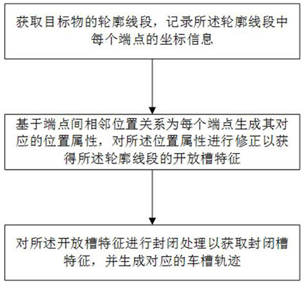
[0044] This embodiment provides a knife rail generation method for automatic identification slot feature, and the part is trough to obtain a corresponding groove trajectory, which reduces the operation of the user manually draw or selects the characteristics of the slot, reducing the user's workload, and improve programming Work efficiency.

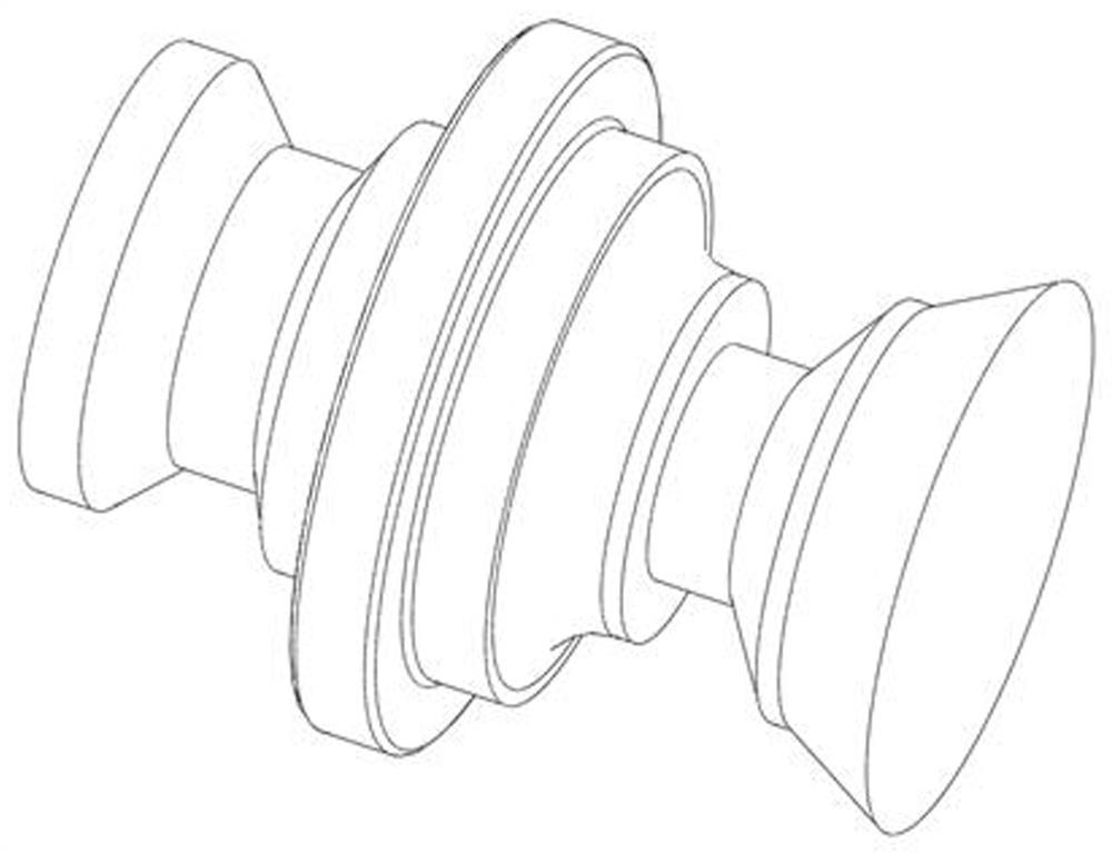
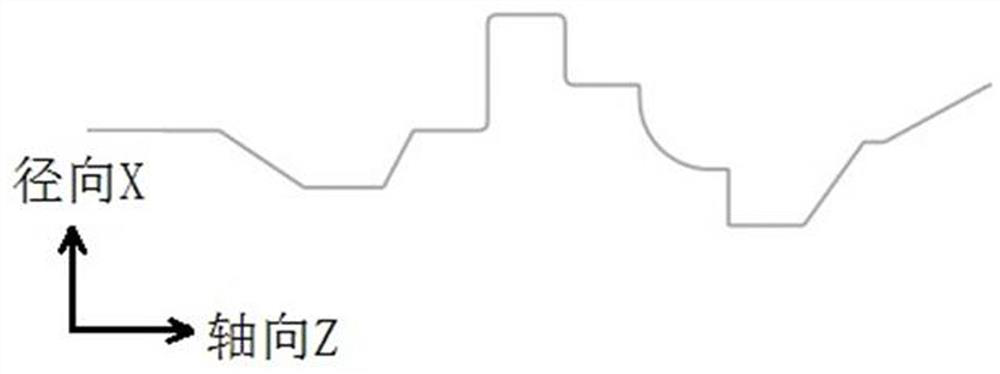
[0045] Such as figure 1 , Figure 10 As shown, the method of identifying tank features in this embodiment includes the steps of:

[0046] Step S1: Obtain the outline segment of the target, record the coordinate information of each endpoint in the outline segment;

[0047] Step S2: Based on the adjacent position relationship between the endpoints, each end point generates its corresponding position attribute, correcting the position attribute to obtain open slot characteristics of the outline segment;

[0048] Step S3: The open slot feature is closed to acquire the closed groove characteristics, and the corresponding groove trajectory is genera...

Embodiment 2

[0077] This embodiment provides an electronic device comprising a processor, a memory, and a computer program stored on the memory and can run on the processor, the processor implements the computer program. Automatic identification slot feature knife rail generation method; further, the present embodiment also provides a storage medium that stores a computer program that implements the above-described automatic identification slot feature.


PUM


Abstract

The invention discloses a tool path generation method and device capable of automatically recognizing groove features and a storage medium, and a part groove machining method comprises the steps that a contour line segment of a target object is obtained, and coordinate information of each end point in the contour line segment is recorded; generating a corresponding position attribute for each endpoint based on the adjacent position relationship between the endpoints, and correcting the position attributes to obtain the open slot characteristics of the contour line segment; and carrying out closing processing on the open groove characteristics to obtain closed groove characteristics, and generating a corresponding turning groove track. According to the method, after the contour line segment of the target object is obtained, all the groove features of the contour line segment are automatically generated according to the attribute relation between each end point and the adjacent end point in the contour line segment, and the corresponding groove turning track is generated according to the groove features, so that the target object can be cut; the operation of manually drawing or selecting slot characteristics by a user is reduced during the period, the workload of the user is reduced, and the programming working efficiency is improved.

Description

Technical field [0001] The present invention relates to the field of turning processing, and more particularly to a knife rail generation method, apparatus, and storage medium of automatic identification tank characteristics. Background technique [0002] At this stage, turning machining is a method of cutting processing on the workpiece relative to the tool rotation on the lathe, which is the most widely used machine tool processing in the machine manufacturing and in the factory, and the most common cutting method is occupied. A very important status. When the rotary body is rotated at high speed, the tool is near the part boundary in the radial direction, and the blank material is touched to remove the body of the processing tank. [0003] The shape characteristics of the outer groove feature are low in the middle, high on both sides; and the groove processing trajectory is approaching from the radial X. The programming of the groove processing and the working plane of the mac...

Claims


Application Information

Patent Timeline
Patent Type & Authority Applications(China)
IPC IPC(8): G05B19/19
CPCG05B19/19G05B2219/35396
Inventor 叶锦松甘文峰朱炯炯黄亮李会江冯征文
Owner ZWCAD SOFTWARE CO LTD
Why Eureka
Try Eureka